Industrial humidification offers two fundamental thermodynamic approaches: steam humidification (isothermal) and adiabatic humidification (constant enthalpy). Both produce the same outcome, raising the air's relative humidity, by different energy routes. The steam system pre-heats water and delivers it as vapour; air temperature is preserved, the process is energy-intensive, hygienic, and tightly controllable. The adiabatic system atomises or evaporates water at ambient temperature; it draws heat from the air and cools it, is energy-efficient, sensitive to water quality, and suits wide duct lines. This guide compares the two approaches across eight dimensions and maps applications using the NKT – Nem Kontrol Teknolojileri portfolio, neither approach is absolutely superior to the other; the right choice follows the thermodynamic profile of the application.
Two Core Approaches
The humidification problem can be described in one sentence: raise the amount of water vapour in the air. Nature offers two routes to achieve that increase. The first route (steam (isothermal)) pre-heats water to its boiling point and injects the resulting water vapour into the air. The second route (adiabatic (constant enthalpy)) delivers water as liquid droplets at ambient temperature and lets evaporation pull heat from the air. Both routes end at the same outcome (the air becomes humidified) but the path curve is thermodynamically different.
This thermodynamic difference becomes clearer through dew point and absolute humidity. In the steam system the water has already changed phase, so the heat input to the air is high; air temperature stays effectively constant, absolute humidity rises. In the adiabatic system water transitions from liquid to vapour and draws its latent heat (about 2,450 kJ/kg at room temperature) from the air; the air cools, absolute humidity still rises, and enthalpy (total energy) stays constant. On a psychrometric chart, the steam process appears as a vertical line up; the adiabatic process appears as a sloped line moving up and to the left along the constant-enthalpy (wet-bulb) line.
This thermodynamic difference simultaneously affects eight practical dimensions: energy consumption, hygiene profile, control accuracy, the cooling side-effect, capacity range, maintenance load, water-quality requirement, and the investment/operation cost balance. The right choice picks the approach whose alignment with the application's thermodynamic profile is strongest across those eight axes. If hygiene and a tight band are the priority, steam; if free cooling and low energy are the priority, adiabatic.
How Steam Humidification Works
The steam humidifier pre-heats water to 100°C and injects the saturated steam through a steam distribution manifold into an HVAC duct or directly into a space. As the steam mixes with the air, much of the latent heat stays in the air; the air does not cool. The process is practically isothermal, dry-bulb temperature shows no measurable change. On a psychrometric chart the air state moves vertically upward.
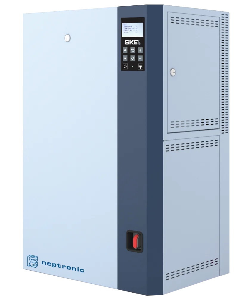
Four architectures exist by steam-generation energy source: electrode (Joule heating via water conductivity), resistive (immersion heating elements inside a stainless-steel steam tank), gas-fired (natural gas or LPG fuel), steam-to-steam (existing high-pressure boiler steam). The NKT catalogue includes resistive (Neptronic SKE4), steam-to-steam (SKS4), gas-fired (SKG4) and direct-injection (SKD); electrode units are not in the portfolio. Common to all steam solutions: isothermal process, high hygiene, tight control band (±1% RH), and relatively high energy consumption.
Electric steam solutions use about 0.75 kWh/kg of electricity for steam; heating water from 20 °C to 100 °C and evaporating it takes ≈ 2,592 kJ/kg ≈ 0.72 kWh/kg. A 45 kg/h unit draws about 34 kW of electricity. In facilities with natural gas, SKG4 gas-fired units move this load to gas; where boiler steam exists, the SKS4 steam-to-steam unit produces clean steam from it. The claim that "steam systems are energy-intensive" is therefore incomplete without looking at the architecture.
How Adiabatic Humidification Works
The adiabatic humidifier delivers water to the air as small droplets at ambient temperature. As soon as a droplet contacts the air, it starts to evaporate; vaporising each gram of water requires roughly 2,450 J of heat at room temperature (latent heat of vaporisation). This heat is drawn from the air; the air cools, absolute humidity rises, and total enthalpy stays constant. On a psychrometric chart the process appears as a sloped line up and to the left along the constant-enthalpy (wet-bulb) line. Every 1 g/kg added drops air temperature by roughly 2.5°C.
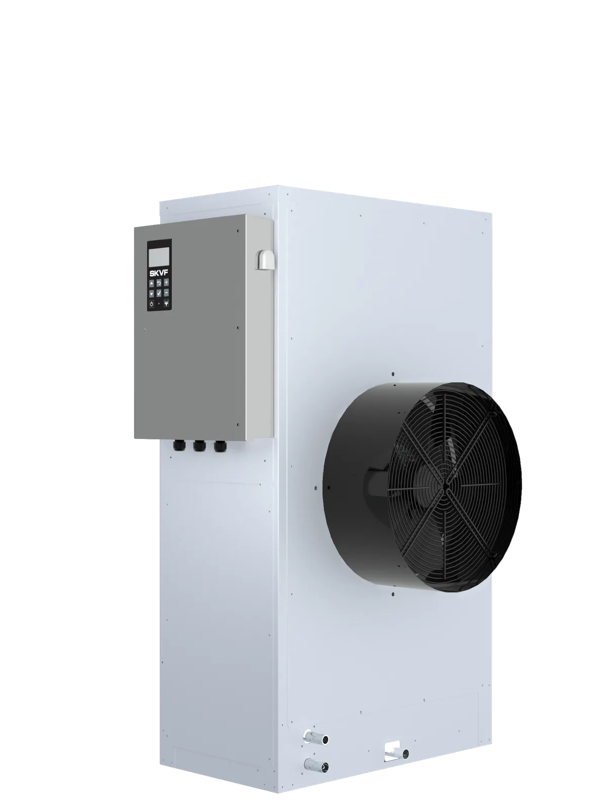
Adiabatic technologies split into four families: high-pressure atomisation (water atomised at a nozzle at 70 bar), evaporative panels (water flows over a cellulose / glass-fibre mat through which the air passes), ultrasonic (a piezo crystal vibrates the water surface at high frequency to produce mist), compressed-air + water atomisation (twin-fluid). The NKT catalogue includes high-pressure atomisation (Neptronic SKH), evaporative cooler (SKVF) and evaporative humidifier (SKV).
In adiabatic systems electricity is spent only on pressurising or atomising the water (pump/fan). The heat of evaporation (≈ 0.68 kWh/kg) is drawn from the air: in summer this is a cooling gain, while in winter the same energy is returned by reheat if the indoor temperature is held constant. On the water-quality axis, RO/DI feed is recommended for adiabatic systems (mandatory on the SKH-100); otherwise minerals in the water are released into the air stream and the system risks biofilm growth and mineral-dust accumulation. To manage Legionella risk, design integrates UV disinfection, filtration and stagnant-water prevention as a whole.
Energy Comparison
The most visible difference between the two approaches is energy consumption. Steam systems structurally must pre-heat the water; adiabatic systems leave the heating to the air. That difference can multiply the annual electricity bill on large-capacity sites.
Figure 1. Steam vs Adiabatic: Energy Flow
| Dimension | Steam (45 kg/h) | Adiabatic (45 kg/h) |
|---|---|---|
| Energy | ≈ 0.75 kWh/kg electricity | Electricity for pump/fan only; ≈ 0.68 kWh/kg heat from the air |
| Unit energy load (45 kg/h) | ≈ 34 kW electric | Pump/fan electricity + ≈ 31 kW heat from the air |
| Winter energy balance | Energy from electricity | Reheat equal to the heat of evaporation |
| Thermodynamic process | Isothermal (vertical) | Constant enthalpy (sloped up-left) |
| Air-temperature effect | Stable | Cools (1 g/kg ≈ -2.5°C) |
| Summer side gain | None | Free cooling |
| Winter side effect | None | Reheat may be needed |
Hygiene Comparison
The two approaches differ structurally on hygiene. In the steam system water reaches 100°C; at that temperature bacterial and viral pathogens are thermally inactivated. The output steam is practically mineral-free. In the adiabatic system water is delivered as liquid droplets; there is no thermal inactivation. Therefore, in adiabatic design, water quality, biofilm prevention and Legionella control are core parts of the design.
| Hygiene Dimension | Steam | Adiabatic |
|---|---|---|
| Thermal inactivation | Yes (100°C) | None (ambient temperature) |
| Mineral content | Practically zero | Depends on water; RO/DI recommended |
| Legionella risk | Structurally absent | Managed in design (UV, filtration, heating) |
| Biofilm risk | None | Risk at stagnant-water points |
| Sterile-space suitability | Standard solution | Limited; specific applications only |
| Hygiene references | VDI 6022, EN 16798 | VDI 6022, REHVA Guidebook 8 |
Steam is generally preferred in hospitals, cGMP pharma, ICH stability cabinets, museum collection spaces and food hygiene-class areas (standards do not prescribe a specific technology). Adiabatic is preferred either in comfort spaces (hospital waiting halls, cafeterias) or in large-capacity specialised applications (textile spinning, wood drying); in every case the design integrates UV-C disinfection, RO/DI feed, automated drainage and periodic microbiological analysis.
Control Accuracy and Process Stability
Control accuracy (how tight a band RH can be held around set point) arises from the different mechanical response times of the two approaches. Steam systems continuously modulate the electrical or gas heat input via SSR or servo valves; response time is in seconds. Combined with a resistive SKE4, ±1% RH is structurally achievable. In adiabatic systems modulation comes from water flow at the atomising nozzles; response time is relatively slower, and tight bands depend on zoning, sensor placement and absorption-distance optimisation.
- ±1% RH need → Steam (resistive SKE4) is the structural pick; SSR + PID combination.
- ±2-3% RH need → Precision print, museums, cGMP rooms; steam is typical, well-designed adiabatic is also possible.
- ±5% RH need → Comfort, general HVAC, warehouse; either approach fits, decide on economics.
- ±5-10% RH band → Textile, wood, print conditioning, agriculture; adiabatic is widely used.
For process stability, steam systems are independent of water-quality swings (especially resistive SKE4); adiabatic systems can be affected by changes in feed-water TDS, hardness and temperature. RO/DI feed, pressure stability, and a nozzle-maintenance schedule preserve adiabatic stability.
Cooling Effect
The cooling side-effect of the adiabatic process turns into a gain or a loss depending on application. Every 1 g/kg added drops air temperature by roughly 2.5°C. In summer this is "free cooling", it offsets chiller load. In winter it requires reheat compensation, typically managed with an additional HVAC coil.
Δh ≈ 0 (constant-enthalpy process)
Example: 22°C / RH 30% (4.9 g/kg) → 22°C / RH 50% (8.2 g/kg)
Δx ≈ 3.3 g/kg → adiabatic T_out ≈ 22 - 8.3 ≈ 13.7°C
Figure 2. Psychrometric Chart: Steam vs Adiabatic Process
The steam system has no such side-effect; air temperature is preserved. In large-volume spaces (textile spinning, wood drying, greenhouses, logistics warehouses) the adiabatic cooling side-gain can be the main decision driver alone. In hospitals, museums, pharma and data centres, where temperature must also be held in a tight band, this side-effect is unwanted and steam is preferred.
Investment, Maintenance, Operation
The CAPEX/OPEX profile of the two approaches differs by capacity and application type. At small-to-medium capacities (below 50 kg/h) steam systems usually start at lower CAPEX; at large capacities (above 200 kg/h) adiabatic becomes substantially more economical. Both approaches require annual periodic maintenance, but the workload distribution differs.
| Dimension | Steam (SKE4) | Adiabatic (SKH) |
|---|---|---|
| CAPEX (45 kg/h) | Medium-high | High (pump station + nozzle line) |
| CAPEX (500+ kg/h) | Very high | Medium, scale economy |
| Annual energy cost | ≈ 0.75 kWh/kg × kg × electricity tariff | Pump/fan electricity + winter reheat (at the heat source's tariff) − summer cooling gain |
| Consumables | SKE4: none; electrode would need cylinders | Nozzle, filter, UV lamp |
| Annual maintenance labour | Periodic chamber cleaning | Periodic nozzle check + RO/UV service |
| Water consumption | 1 L water = 1 kg steam + drain | 1.1-1.2 L water / 1 kg moisture + bleed |
| 10-year OPEX direction | Energy dominant | RO/DI and nozzle maintenance dominant |
It is not correct to claim an approach is "always cheaper" across capacity scales. For a small print room needing a tight band the resistive SKE4 is usually more economical, while for a textile plant with a load of several hundred kg/h and a summer cooling need the adiabatic solution usually is; the difference must be calculated from the facility's energy prices. The right choice is made by looking holistically at capacity × tariff × hours × hygiene class × control band.
Steam: Which Applications?
Steam systems are the structural pick for the application profiles below; in these profiles adiabatic falls short on hygiene, control band, or temperature preservation.
- Hospital operating theatres: 20–60% RH per ASHRAE 170; mineral-free steam is preferred for hygiene.
- Pharma and cGMP production: Tablet, capsule, gelatin rooms; ICH Q1A stability cabinets; ±5% RH test tolerance on stability cabinets; mineral-free steam preferred.
- Museum, archive, library: a tight RH band set for the collection and a limited daily change; ±2% RH control band.
- Precision print: Offset press room, paper storage; ±3% RH and static control.
- High-density data centre: stable humidity control within the ASHRAE TC9.9 envelope → resistive + RO.
- Precision electronics: ESD protection and ±2% RH band.
- Optical / precision mechanical: ±2% RH and below; structural guarantee.
Neptronic SKE4 Resistive Steam: Product Recommendation
Adiabatic: Which Applications?
Adiabatic systems are the structural pick for the application profiles below, especially where high capacity, free cooling and low energy shift the balance.
- Textile spinning and weaving: several hundred kg/h capacity, ±5% RH acceptable, summer cooling gain.
- Wood drying and conditioning: Large volumes, no tight band required, homogeneous droplet distribution.
- Paper production and print conditioning: Large production halls, ±5-8% RH acceptable.
- Greenhouse and vertical farming: Free cooling + humidity rise together.
- Logistics warehouse and cold storage: Balanced RH and temperature-lowering side-gain.
- Medium-density data centre: Adiabatic integrated into a free-cooling strategy.
- Large-area / large-volume: Industrial hangars, automotive paint shops, steel-mill cooling.
- Livestock and free-range housing: Summer cooling and humidity control.
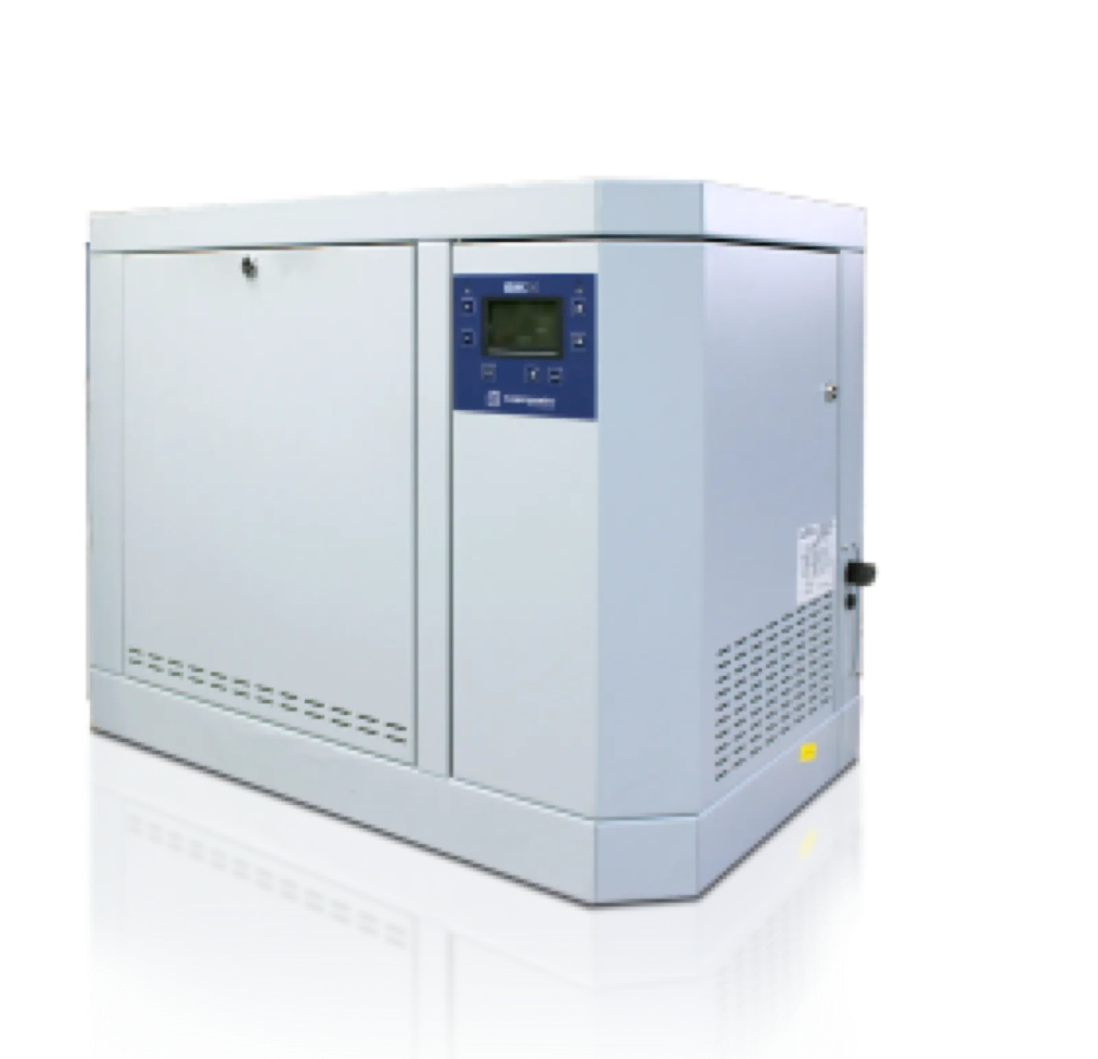
Neptronic SKH High-Pressure Atomisation: Product Recommendation
Detailed Comparison Table
A side-by-side comparison of the two approaches across 11 dimensions follows.
| Criterion | Steam (Neptronic SKE4) | Adiabatic (Neptronic SKH) |
|---|---|---|
| Thermodynamic process | Isothermal (constant T) | Constant enthalpy (T drops) |
| Energy | ≈ 0.75 kWh/kg electricity | Electricity for pump/fan only; ≈ 0.68 kWh/kg heat from the air |
| Typical control band | ±1% RH (PID + SSR) | ±3-5% RH (tighter with zoning) |
| Hygiene profile | Thermal inactivation | Managed by design (UV/RO/filter) |
| Water-quality requirement | SKE4: every type incl. RO/DI | RO/DI recommended |
| Air-temperature effect | Stays constant | Cools (-2.5°C / g/kg) |
| Capacity range | 5–120 kg/h (SKE4, 50 Hz) | 20–100 kg/h per unit (SKH, 3 models) |
| Scale-economy direction | Small-medium advantageous | Advantageous at large capacities |
| Summer side gain | None | Free cooling |
| Winter side effect | None | Reheat may be needed |
| Typical application | Hospital, pharma, museum, print, data centre | Textile, wood, greenhouse, logistics, large volumes |
NKT Engineering Approach
As NKT – Nem Kontrol Teknolojileri, we are the authorised Turkish distributor of Neptronic humidifiers; we provide equipment supply, technical support in equipment selection, technical service and spare parts. Engineering design, installation and commissioning are within the scope of the facility's design engineer and installer. Steam and adiabatic approaches are complementary, not competing. In a typical medium-to-large facility both technologies run together in different rooms of the same building: steam SKE4 for the operating theatre or cGMP room, adiabatic SKH/SKVF for packaging or general HVAC. The main portfolio solutions map as follows:
- SKE4, Resistive steam (5–120 kg/h, 50 Hz). Hygienic, tight band, isothermal.
- SKS4, Steam-to-steam. Existing boiler steam; clean steam.
- SKG4, Gas-fired steam. High capacity + natural gas.
- SKD, Direct steam injection and distribution manifolds.
- SKH, High-pressure atomisation adiabatic. Large volumes, low energy, free cooling.
- SKV / SKVF, Evaporative humidifier and evaporative cooler. Wide duct lines, low-pressure.
A typical project includes (1) space analysis and water sampling, (2) target definition (RH band, hygiene class, temperature tolerance), (3) load calculation (psychrometric), (4) approach selection (steam / adiabatic / hybrid), (5) equipment selection, (6) installation and commissioning. NKT provides technical support for equipment selection at steps (3)–(5); installation and commissioning fall within the scope of the installer and design engineer.
Engineering View for the Right Choice
Steam and adiabatic humidification reach the same target via different thermodynamic routes. "Which is better?" gives the right answer when phrased correctly: which one matches my application? Hygiene, a tight control band, temperature preservation and a mineral-free steam need point to steam; large volumes, low energy, the free-cooling side gain and large capacities point to adiabatic. The two approaches are not interchangeable, they are designed for different application profiles.
In a significant share of modern facilities a single approach is not enough; in a typical medium-to-large facility both technologies run together. This co-operation should be treated as part of the design from the outset: which room is fed by which approach, RH band tolerances, temperature-preservation conditions and the 10-year TCO equation are evaluated together. The right choice does not start with a device brand, it starts with reading the thermodynamic profile correctly. The device comes last, as the final step of the engineering analysis.