Central humidification produces moisture at a single point in the HVAC air handling unit (AHU) and distributes that conditioned air across multiple building zones through a duct network. Local humidification delivers moisture directly to the room or process space, typically through a ceiling-mounted unit, a standalone in-room solution, or a small dedicated air loop, without depending on the main duct network. The choice often looks like a simple cost-capacity-energy trade-off in comfort applications; but in industrial humidification and precision climate control, once zone diversity, sensor placement, hygiene, pressure cascade and control band enter the equation, it becomes a multi-layered architectural decision. This guide compares the two architectures across 14 dimensions and turns the decision matrix into a site-engineering-grade reference.
Definition of Central and Local Humidification
Central humidification is an architecture where moisture is produced at a single point (typically the HVAC supply duct or post-AHU mixing chamber) and distributed across multiple rooms in the building through a duct network. Typical components: one or more steam/atomization humidifiers, a steam distribution manifold or atomization rack, duct sensors, a high-limit sensor, and a BMS interface. Operating logic: single production, multiple distribution.
Local humidification, by contrast, delivers moisture directly into the conditioned space or into a small dedicated air loop serving that space, rather than humidifying the air sent toward the room. The unit may be a ceiling-mounted module, an in-room standalone fan + nozzle solution, an in-cabinet monoblock atomizer, or a small fan-coil retrofit. Operating logic: every room has its own moisture production point. A third hybrid path is also possible (central coarse moisture + local trim) which is frequently chosen for large museums, multi-cGMP-room pharmaceutical sites and data centers.
How Central Humidification Works
In a central architecture, supply air passes through the AHU (filter, heater/cooler, fan in sequence) and is humidified at a steam distribution rack or atomization manifold downstream of the fan. In steam systems, moisture fully mixes with air after travelling 1-2 meters of absorption distance carried by duct velocity. With adiabatic humidification, depending on droplet size, a 2-4 meter absorption length is designed. The RH of air arriving at the rooms is read by a reference sensor located in the room's return duct, and the PID controller modulates humidifier capacity by comparing that value against the set-point.
When a single humidifier distributes to many zones, each zone's moisture demand may differ. In that case the central unit operates against an "average" demand; inter-zone fine-tuning is provided by VAV boxes, post-heat or per-zone trim units. The absolute goal of "every zone in its own optimum band" is technically limited in pure central architecture.
How Local Humidification Works
In local humidification, the production point is close to the room; the unit either sits in the room or connects to a small air loop dedicated to that space. Adiabatic standalone units disperse water droplets via a fan + atomization nozzle combination inside the room; if droplet size is kept around 10-20 microns, the droplets fully evaporate without wetting surfaces. In steam-based local solutions, a low-capacity (5-15 kg/h) unit is suspended from the ceiling and delivers steam directly to the room; this method is used in hospital isolation rooms, small museum vitrines, lab test cabinets and specialty storage rooms.
Local control is typically a closed loop confined to the room: "room sensor → unit's own PID → modulation". This turns zone flexibility into an advantage, each room runs at its own set-point. However, local architecture also brings equipment multiplication. N rooms means N units, N sensors, N supply lines, N service appointments. Facility operations must manage this multiplication through BMS integration, a unified service calendar and standardized equipment types.
| Typical Local Solution | Capacity Range | Typical Application |
|---|---|---|
| Ceiling-mounted adiabatic (high-pressure atomization) | 2 – 30 kg/h | Textile shop floor, woodshop, warehouse |
| Standalone evaporative cooler/humidifier | 200 – 3,000 m³/h | Logistics warehouse, parking, small production |
| In-room compact steam (resistive) | 5 – 15 kg/h | Museum vitrine, small lab, isolation room |
| In-cabinet monoblock atomization | 1 – 10 kg/h | Maturation chamber, QC cabinet |
Advantages of Central Humidification
Central architecture naturally turns concentration of production and control into advantage. Per-unit-capacity investment and maintenance costs benefit from scale economy when concentrated at one point; a single BMS connection, a single feed-water line, a single water-treatment station and a single maintenance appointment dramatically simplify the operating logic of a multi-room building. Because equipment is invisible in the rooms, interior design and hygienic use are also achieved without friction.
Risks of Central Humidification
Central architecture amplifies single-point-of-failure risk along with scale. If the central humidifier goes offline, all served zones are affected; in critical facilities this mandates a redundant (N+1) unit or two parallel-line design. When the duct network is long, part of the transported steam condenses on the duct wall, this loss requires condensate drainage and adds an energy line-item.
Zone demand diversity is the second structural risk. If one section has high humidity demand and another has low, the central unit operates to the average; the low-demand zone gets over-humidified and the high-demand zone is under-humidified. Closing this mismatch requires per-zone trim or VAV damper control, but pure central architecture provides this granularity only to a limited extent. The third risk is in the hygienic context: if moisture distributes through a single duct network, a biological contamination event in any room (such as aerosol generated in a patient room) can reach the central humidifier's return air loop. For this reason, classified spaces in hospital and pharmaceutical facilities are assigned their own AHUs as a matter of good engineering practice.
| Risk Axis | Impact | Mitigation | Consequence |
|---|---|---|---|
| Single-point failure | All zones affected | N+1 redundancy, parallel line | CAPEX ↑ |
| Duct condensate | Steam loss + hygiene risk | Insulated duct, condensate drain | Maintenance ↑ |
| Zone demand mismatch | Over/under humidification | Zone trim, VAV damper | Complexity ↑ |
| Cross-contamination | Hygiene class drops | Class-based dedicated AHU | AHU count ↑ |
| Long-duct loss | Setpoint not reached | Higher-capacity selection | Energy ↑ |
| Commissioning complexity | Test time extends | Multi-zone airflow test | Process ↑ |
Advantages of Local Humidification
Local humidification structurally embeds zone flexibility. Each room runs at its own set-point; a user can raise the RH band of one room without affecting its neighbor. This capability is critical in scenarios like museum gallery rotation, pharmaceutical campaign changeover and hospital room-use flexibility. When a local unit fails, service interruption is confined to that specific room, other zones remain unaffected.
The second advantage is the absence (or shortness) of duct runs. With in-room production, contact between steam or droplet and duct wall is minimal; condensate, microbial growth surface and steam line losses are largely eliminated. The third advantage is fast response, the room reacts within seconds to a set-point change; in central systems the same response takes minutes because the duct network introduces a 1-2 minute transport lag.
Risks of Local Humidification
Local architecture multiplies equipment count by the number of rooms. A 20-room facility means 20 units, 20 sensors, 20 service visits and potentially 20 different BMS nodes. This multiplication scales total investment cost, maintenance workload and spare-parts logistics. Non-standard room sizes may also force equipment-type diversity; which raises the operations team's technical knowledge burden.
The second risk is equipment visibility inside the room. Ceiling-suspended or floor-standing units can impose interior design constraints; noise level (particularly the pump skid of a high-pressure atomization system) may be uncomfortable for the occupant. In silence-critical spaces such as hospital patient rooms, low-pressure evaporative or compact steam is preferred over local atomization.
Zone Control and Multi-Zone Design
In a multi-zone building, the decision is made between pure central, pure local or hybrid models. Pure central makes sense when zone RH bands are close and a single set-point average is acceptable. Pure local is preferred when there is a large difference between zone RH bands or when hygienic classification requires a separate production point for each zone. The hybrid model (central coarse + local trim) combines the advantages of both worlds in large facilities.
| Zone Profile | RH Difference | Recommended Architecture | Typical Example |
|---|---|---|---|
| Homogeneous zones (single profile) | ≤ 5% RH | Central | Office floor, retail |
| Slightly varied zones | 5 – 10% RH | Central + zone trim | Data center, hospital corridor |
| Clearly varied zones | 10 – 20% RH | Hybrid (central coarse + local trim) | Pharma site, museum storage+gallery |
| Fully heterogeneous zones | > 20% RH | Local (per-zone) | Maturation chambers, ICH stability |
How Sensor Placement Affects the Decision
The decision is shaped not only by equipment architecture but also by humidity sensor placement logic. In central architecture, the master sensor sits in the return duct; each zone may additionally have a local room sensor. In local architecture, the sensor is in the room itself, at a point with consistent airflow (away from door swings and nozzle paths). Sensor logic determines which signal the control loop treats as "truth", and this directly affects the achievable tightness of the control band.
The communication layer also influences the decision. In central architecture, all sensors can be carried to BMS via a single device; in local architecture, each zone's sensor becomes a separate BMS node. In facilities with high monitoring density such as data centers or large museums, the local layout offers more measurement points, this is an advantage; at the same time, the additional nodes carry license cost and data-management overhead.
Central Humidification: Typical Applications
Central humidification is the dominant choice in office complexes, malls, hotels, hospital corridors/common areas, university campus buildings and large commercial buildings. In these applications inter-room RH demand is largely homogeneous, there is no hygienic classification, and investment/maintenance economics dominate. In data centers, central architecture + local trim in CRAH/CRAC units is a frequently encountered hybrid layout.
At industrial scale; pharmaceutical packaging areas, the general line area in food processing, the primary ventilation of printing plant production rooms and the CDA + RH cleanroom support spaces of electronic manufacturing are typical central applications. In these applications a steam distribution manifold or multi-nozzle (Multi-Steam) solutions are preferred for in-duct distribution.
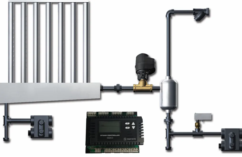
Figure 1. Central Humidification Schematic: Steam Distribution at the AHU
Local Humidification: Typical Applications
Local humidification stands out in single-room concentrated applications, multi-zone but heterogeneous facilities, large open spaces where duct installation is uneconomic and process rooms requiring fast response. Textile shop floors (1,500-3,000 m² in a single volume), woodshops, logistics-warehouse climate control, underground parking and evaporative cooling are the typical domain of local architecture.
In more sensitive applications the local solution becomes part of a hybrid: small steam humidifier inside a museum gallery + central AHU; local trim in pharmaceutical packaging + central coarse; standalone room humidifier in hospital isolation + class-based AHU. In these applications the local unit provides per-room set-point flexibility.
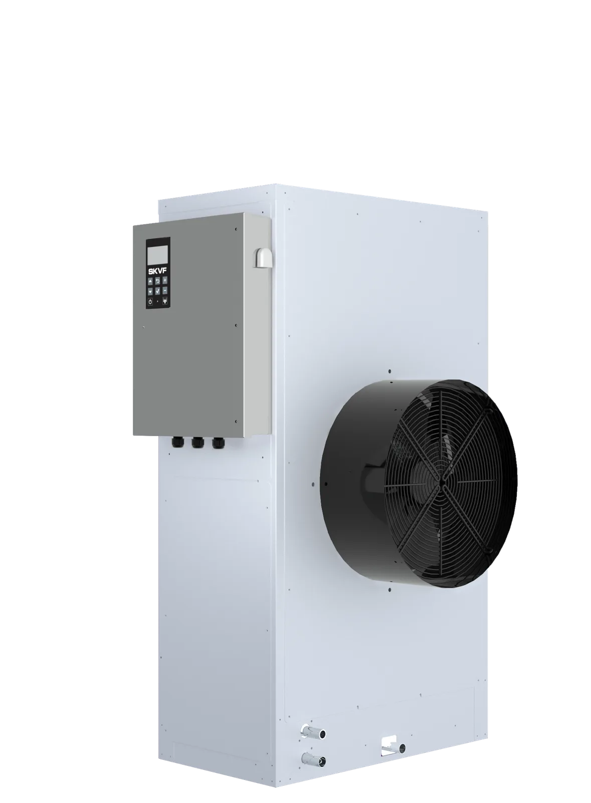
Figure 2. Central vs Local Architecture: Comparison Matrix
10-Criterion Comparison Table
The table below places central and local architectures side by side across 10 dimensions. All dimensions should be considered together when deciding on a project; the weighting depends on the application.
| Criterion | Central | Local |
|---|---|---|
| CAPEX (per unit capacity) | Low (scale economy | High) equipment multiplies |
| Annual maintenance load | Low (single visit | High) N visits |
| Water treatment | Single RO/softener | Distributed or per-unit |
| BMS node count | Few (single device | Many) per-zone |
| Zone flexibility (different RH bands) | Limited | High, each zone independent |
| Response time (set-point change) | Minutes | Seconds-tens of seconds |
| Single-point failure impact | All zones affected | Only that room affected |
| Duct condensate / line loss | 3-8% range loss | Negligible |
| Cross-contamination risk | Present, classification needed | Structurally low |
| Typical application profile | Office, mall, hotel, corridor | Textile, warehouse, gallery, isolation |
NKT Approach
NKT Humidity Control Technologies always makes the central/local decision based on site analysis + psychrometric calculation. The standard project flow is: (1) Room list with RH band, hygiene class, capacity and maximum duct length per room; (2) Inter-zone RH band homogeneity assessment; (3) Analysis of facility BMS topology and existing infrastructure (boiler steam, natural gas, RO/softening); (4) A recommendation based on the decision matrix, pure central, pure local or hybrid; (5) 10-year TCO calculation and finalization of the architectural decision.
The portfolio offers SKD steam distribution manifolds for central architecture, SKVF standalone evaporative cooler/humidifier and SKV evaporative-media in-room humidifiers for local architecture; for high-pressure atomization applications, the SKH series can be configured both centrally and locally.
Closing Assessment
Central and local humidification are not alternatives to each other but two architectures that answer different facility profiles. Central architecture is the dominant choice in offices, malls, hotels, hospital corridors and general commercial buildings thanks to scale economy, single BMS node and water-treatment consolidation. Local architecture stands out in facilities with heterogeneous zones, in large open volumes and in sensitive rooms with its zone flexibility, fast response and low cross-contamination risk. The hybrid layout (central coarse + local trim) combines the advantages of both worlds at large scale.
The right decision begins at project kickoff with three questions: (1) What is the RH band difference between zones? (2) Does hygienic classification require a separate production point for each zone? (3) Which architecture better matches the facility's BMS, water and energy infrastructure? Combining these three questions with psychrometric calculation and 10-year TCO turns the architectural decision into an engineering-based (not emotion-based) outcome. Correct use of concepts such as relative humidity, absolute humidity, dew point and high-limit sensor raises the reliability of that decision. The NKT engineering team feeds the decision matrix with site data and clarifies the balance between investment and operation at project kickoff.