Pillar / Design Guide
Selecting a humidifier is not simply a kg/h capacity match; field experience shows that the vast majority of post-commissioning issues stem not from device brand or model but from systematic design decisions made wrong on paper. Wrong sensor location, missing absorption distance, on/off control, skipped water analysis and BMS integration added as an afterthought, these five items account for 80% of humidity complaints on service-call logs. This pillar guide walks through the 10 most common mistakes in industrial humidification projects, grouped under sensor placement, PID control, condensation and drain, and offers a one-paragraph CORRECT APPROACH for each.
Why Capacity Alone Is Not Enough
When a humidification calculation produces 60 kg/h, ordering "a 60 kg/h device" does not by itself yield a working system. Even with correct capacity, if the sensor sits in the wrong location the device always reads the wrong value; if absorption distance is skipped, the duct wall develops condensate; if on/off control is chosen, room RH swings within a ±8% band. In short, correct capacity + wrong design = perpetual complaint.
This guide systematises the 10 typical mistakes derived from manufacturer service-call records. Most can be prevented with cheap measures at the design table, yet correction costs after commissioning rise 5-20×. Thirty minutes spent on a checklist at the design desk prevents three days of on-site intervention.
Figure 1. 10 Typical Humidifier Selection Mistakes: Summary Map
Mistake #1: Only Looking at kg/h Capacity
TYPICAL ERROR: The project designer pulls a kg/h figure from a table using only design airflow and target RH; fresh-air ratio, dry-bulb temperature, humidity ratio delta, simultaneity coefficient and safety margin are crammed into a single step. CONSEQUENCE: The result undershoots or overshoots actual need by 20-40%. Small output misses winter setpoint; large output cycles on/off continuously and shortens cylinder / nozzle life.
CORRECT APPROACH: A proper humidification capacity calculation uses outdoor airflow m³/h, winter design temperature, winter design humidity ratio, indoor target RH and indoor target T via absolute-humidity-difference: Q (kg/h) = ρ × V × (x_in − x_out). Add 15-20% safety margin; pick a device that preserves the modulation range (minimum 10:1 turndown).
Mistake #2: Water Analysis Is Skipped
TYPICAL ERROR: Under the assumption "we'll use city water, it'll be fine", device technology is chosen without measurements of hardness, conductivity, chloride, silica, alkalinity and TDS. CONSEQUENCE: An electrode unit on an RO/DI line will not run; hard mains water in an electrode unit drops cylinder life to 6-10 months; high-silica well water doubles maintenance load via scaling and foaming for both technologies.
CORRECT APPROACH: Before the purchase decision, measure at least six parameters at a certified lab, conductivity (μS/cm), hardness (°fH), TDS (mg/L), chloride, silica, alkalinity. For sensitive sites add pH. Adiabatic atomisation systems require RO water or deionised water for hygiene.
Mistake #3: Skipping Absorption Distance
TYPICAL ERROR: The steam manifold is mounted in the duct but the required downstream clearance is not specified in the project; the first elbow is 80 cm away, a heating coil at 1.2 m, a filter at 1.5 m. CONSEQUENCE: Steam condenses onto the nozzle and filter surfaces, causing dripping, corrosion, filter-media degradation and microbiological growth.
CORRECT APPROACH: Minimum upstream and downstream clearances around the steam manifold are calculated; typical design 1-2 m downstream. Multi-Steam multi-nozzle manifolds in large duct cross-sections can shorten the distance to 0.5 m. Distance formula: L ≈ k × (steam flow / duct velocity) × (ΔRH / ΔT); k is manufacturer- and nozzle-pattern specific.
Mistake #4: Duct Velocity Is Ignored
TYPICAL ERROR: Duct velocity sits at low values like 1.5 m/s; the design needs a long absorption distance and steam settles in the duct floor. CONSEQUENCE: Wall dripping, corrosion, duct-gasket leaks, filter degradation. At high velocity (>8 m/s) steam droplets pass elbows before fully evaporating, delivering wet air downstream.
CORRECT APPROACH: Ideal duct velocity is 2.5-5 m/s; this band keeps absorption distance reasonable and pressure drop low. If velocity is <2 m/s, reduce duct cross-section; if >6 m/s, use wider-angle nozzle patterns. With fixed airflow and large duct cross-section, inject steam at the duct centre line and perpendicular to airflow.
| Duct Velocity | Absorption Effect | Design Action |
|---|---|---|
| < 2 m/s | Lengthens, dripping risk | Reduce duct or use Multi-Steam |
| 2.5 – 5 m/s | Ideal (1-2 m absorption | Standard SKD or distribution manifold |
| 5 – 7 m/s | Shortens) homogeneity drops | Wider-angle nozzle, mount near top |
| > 8 m/s | Droplet carryover, wet downstream | Reduce velocity or add droplet eliminator |
Mistake #5: Poor Drain Design
TYPICAL ERROR: The device drain is plumbed directly to the nearest floor drain; slope, air gap, siphon and hot-water-compatible piping are ignored. CONSEQUENCE: Floor-drain odour back-pressure, hot drain water deforming PVC, back-siphon reaching electronic boards (out-of-warranty failure). Legionella risk also rises without an air gap.
CORRECT APPROACH: Per ASME and EN 1717, an air gap between device drain outlet and floor drain is mandatory, the gap must be at least two pipe diameters. Pipe material must suit the device drain temperature (>80°C), CPVC or stainless steel; minimum 2% slope; sealed siphon and a cleanout cap on the line.
Mistake #6: Wrong Sensor Placement
TYPICAL ERROR: The RH sensor is mounted directly in front of the supply diffuser where the airstream hits it; or in the room near an exterior door, above a heat source (radiator), in a spot the sun moves over during the day. CONSEQUENCE: The device always reads wrong, in front of the diffuser it reads un-absorbed steam and reduces output; near the door it sees a setpoint deviation at every opening; above a heat source it under-reads true RH.
CORRECT APPROACH: Sensor placement logic is defined for four sensor types: room sensor (representative middle point), duct sensor (in return air), supply sensor + high-limit (after absorption), process-point sensor (right beside a critical machine). The diagram below illustrates a typical facility with all four sensor types correctly placed.
Figure 2. Sensor Placement Diagram: Room / Duct / Supply / Process
WRONG Sensor Location
- Directly in front of the supply diffuser
- Within 1 m of an exterior door
- Above a radiator or window
- Too close to the ceiling (hot-air layer)
- Below 50 cm from the floor
- On a sun-exposed wall that changes over the day
RIGHT Sensor Location
- Representative middle point of the room
- 1.5-1.8 m above the floor
- At least 2 m from doors and airflow
- Minimum 1 m from heat sources
- On a wall not exposed to direct sun
- Balanced point between supply and return
Room Sensor Placement
The room sensor reports the representative condition of the space to the PID controller. Correct location is the middle point of the room at 1.5-1.8 m above the floor (breathing height), away from direct airflow, heat sources, windows and direct sun. A single sensor is not always enough, for spaces over ~120 m² the correct reading is the average of two points.
In sensitive spaces (GMP, hospital theatre, museum) sensor location must be documented in the validation report; periodic (annual) calibration is required. Wrong placement does not only break control, it can also invalidate quality records.
| Sensor Type | Location | Role | Typical Use |
|---|---|---|---|
| Room sensor | Room middle, 1.5-1.8 m above floor | RH setpoint control | Comfort, office, storage |
| Duct sensor | Inside return duct | Average RH | Multi-zone shared AHU |
| Supply + High-limit | 0.5-1 m after absorption distance | Supply RH cap + safety | Sensitive spaces, GMP |
| Process point | Beside a critical machine | Local RH control | Print, precision manufacturing |
Duct Sensor
The duct sensor sits in the return duct and represents the average room RH. For multi-zone shared AHUs it can be enough on its own; however, if inter-zone RH variation exceeds 5%, a per-zone room sensor is more accurate. Mounted perpendicular to airflow and at the duct centre line; close to a wall, stratified air gives wrong readings.
In the return duct, temperature is below supply temperature, so RH differs from room RH. The PID controller algorithm must compensate, or the calculation must be referenced to room temperature. Sensor selection should be 4-20 mA and BACnet/Modbus capable.
Supply Sensor and High-Limit
The high-limit sensor sits in the supply duct downstream of the humidifier and at the end of the absorption distance; its job is to keep supply RH below a defined cap (typically 90% RH). Above this cap the humidifier is stopped independently of PID, even if room RH is still below setpoint, this prevents duct-wall condensation.
The high-limit is not just backup safety; it is by design a sub-system. If the device is oversized or PID is mistuned, the high-limit activates and makes the system error visible to the operator. In sensitive sites the high-limit should be exposed to BMS as a separate alarm point.
Process-Point Sensor
The process-point sensor is mounted beside a critical machine (offset print head, tissue sampling chamber, precision weighing booth) and controls local humidity independently of room average RH. It usually feeds a trim loop separate from the main controller for local modulation.
Example: in a print room, average RH may be 50%, but local RH in front of the press head (under hot cylinders) can drop to 35-40%; the process-point sensor catches this and boosts local steam injection. Sensor selection should be capacitive RH + dry-bulb combined type.
Average vs Local Sensor: Which One?
A single sensor (average) is enough for comfort applications; multiple sensors (average + local trim) are mandatory for sensitive processes. Decision criteria: spaces >150 m² need two sensors; if a critical machine is present add a process-point; multi-zone AHUs need a duct sensor per zone + average calculation.
As sensor count grows, calibration load grows; an annual calibration programme must be defined at the design stage. After three years of operation, an uncalibrated sensor can drift 3-7% RH.
Mistake #7: On/Off Control Is Selected
TYPICAL ERROR: On a budget, the device is controlled by an on/off thermostat relay; it runs at full capacity, stops when setpoint is exceeded, restarts when RH falls. CONSEQUENCE: Room RH swings ±5-8%; nearby cylinder electrodes go through continuous heat / cool cycles; electrical connections endure thermo-mechanical fatigue; cylinder life shortens 30-40%.
CORRECT APPROACH: Sensitive sites must use PID control. Modulation should be in the 10-100% band; the device follows space demand linearly. PID tuning is done on site against actual T/RH/volume; PID coefficients differ per facility.
What Is PID Control?
PID (Proportional-Integral-Derivative) is a closed-loop algorithm that simultaneously evaluates current error (P), accumulated error (I) and rate of change (D). Output: u(t) = Kp × e(t) + Ki × ∫e(t)dt + Kd × de/dt. PID is ideal for humidification because RH is both a slow-response parameter and intolerant of overshoot / undershoot.
e(t) = setpoint − measurement; u(t) = modulation output (0-100%)
In modern humidifiers the PID algorithm runs in the device's internal controller; the user only enters setpoint. PID parameters (Kp, Ki, Kd) are calibrated per facility, at commissioning either auto-tune or manual Ziegler-Nichols is applied.
Why Modulation Matters
Modulation is the control behaviour of adjusting device output linearly with space demand. In on/off, output is either 100% or 0%; in a modulating system, it is 10%, 40%, 75%, any value in between. This reduces RH swing to ±1-2% and keeps thermal load on cylinders / nozzles even.
Modulation range (turndown ratio) depends on device technology: resistive steam with SCR is 0-100% continuous; electrode with water-level modulation is 20-100% stepped; SKH atomisation via variable-speed pump is 10-100%. Correct device selection matches modulation needs.
When PID Is Mistuned
Wrong PID coefficients produce three typical issues: (1) Kp too high (overshoot, the system exceeds setpoint by 2-3% then swings back for half a minute; (2) Ki too high) integral wind-up, the system stops late; (3) Kd too high, amplifies sensor noise, device hunts in micro-cycles continuously.
| Parameter | Typical Starting Value | Effect |
|---|---|---|
| Kp (proportional gain) | 5-15 | Response speed; high = overshoot, low = slow |
| Ki (integral time, s) | 120-600 | Zeroes accumulated error; low = wind-up |
| Kd (derivative time, s) | 0-30 | Anticipates change; high = noise amplification |
At commissioning, use auto-tune if available; without it, manual tuning by Ziegler-Nichols or Cohen-Coon. After three months, repeat fine-tuning from the trend log.
Mistake #8: No Maintenance Access
TYPICAL ERROR: The device is dropped into a mechanical room without considering the front clearance needed for cylinder swaps, drain accessibility or LED visibility. The device is 5 cm from the wall, blocked by a pipe on one side, with a duct above. CONSEQUENCE: Cylinder swap requires moving the device; what should be a 30-min annual maintenance turns into 4 hours.
CORRECT APPROACH: Manufacturer-specified minimum clearances must be reflected in the design, typically 60-90 cm front (cylinder extraction), 30-40 cm side, 40 cm top (drain / water supply). Drain cleanout cap must be accessible; the electrical enclosure must open easily for the authorised technician. For side-by-side units, leave at least 50 cm between them.
Mistake #9: Mismatched Water Treatment
TYPICAL ERROR: RO treatment is added to the facility later, but the existing electrode humidifier loop is not changed; the electrode unit does not run on RO. Or sodium-based ion-exchange softening is installed; foaming compounds cause continuous alarms in the electrode cylinder. CONSEQUENCE: The device does not run or runs at half capacity; the facility eventually bypasses the RO loop.
CORRECT APPROACH: Water-treatment + humidifier technology matching is done up front. RO/DI feed → resistive steam or SKH high-pressure atomisation; softened feed → both technologies compatible; hard mains → resistive is preferred (no cylinder cost). For adiabatic atomisation, RO/DI is mandatory for hygiene.
Mistake #10: BMS as an Afterthought
TYPICAL ERROR: The device is installed standalone with a fixed setpoint; BMS integration is "left for phase 2". Later, BACnet/Modbus protocol fit, alarm points, trend log and setpoint scheduling cards are added and wiring is redone. CONSEQUENCE: Extra cost rises 3-7×; certification is delayed; retrospective trend analysis is impossible.
CORRECT APPROACH: BMS integration must be discussed at the design start, protocol choice (BACnet IP or Modbus RTU), alarm points (high-limit, water level, cylinder life, drain failure), trend log requirements (1-min sampling, 1-year retention), setpoint scheduling (time-based setpoint shifts). BMS compatibility is the first criterion in the device shortlist.
WRONG: BMS Later
- Standalone setpoint, manual settings
- No defined alarm points
- No trend log, no retrospective analysis
- Phase-2 card + wiring extra cost
- Certification delay 3-6 months
RIGHT: Integrated Design
- BACnet IP or Modbus RTU chosen up front
- Alarm points listed (8-12 items)
- Trend log 1-min sampling, 1-year retention
- Setpoint scheduling defined
- Commissioning + BMS integration concurrent
Why Condensation Forms
Condensation occurs when air exceeds the maximum moisture it can carry (saturation) or when a surface temperature drops below the air's dew point. Three typical triggers: (1) warm humid air meets a cold surface; (2) steam hits a surface before completing absorption distance; (3) insufficient air mixing pushes local conditions to saturation.
Condensation in a duct means dripping, corrosion, filter degradation and microbiological growth. System design must therefore either accept condensation or prevent it, in hygienic sites, condensation is unacceptable.
Figure 3. Condensation Triggers Diagram
Cold Surface and Dew Point
Water vapour in air condenses onto any surface whose temperature falls below the air's dew point. For 22°C, 50% RH, dew point ≈ 11.3°C; if a surface is colder, condensation is unavoidable. Duct walls, cold windows, exterior facades, AC evaporators are typical cold surfaces.
Prevention: duct insulation, thermal barriers on hot lines, sealing thermal bridges on the facade, reducing airflow on cold spots. Sensitive sites need dew-point meters + alarms.
Wrong Distribution + Short Absorption
If the steam manifold is mounted close to a duct wall rather than at the centre line, steam flow becomes asymmetric, local saturation on one side, insufficient humidification on the other. Elbows, heating coils or filters within 1 m of the nozzle outlet cause steam to hit the surface before absorption completes.
Correct design: manifold at the duct centre, perpendicular to airflow, 1-2 m unobstructed downstream. For large duct cross-sections, Multi-Steam multi-nozzle delivers shorter absorption distance.
Insufficient Air Mixing
At low duct velocity (e.g. 1 m/s) steam accumulates by gravity in the lower half of the duct; the upper half stays dry while the lower half reaches 100% RH and condenses. This is very common in single-nozzle distribution with large ducts.
Solutions: reduce duct cross-section (raise velocity), increase nozzle count with Multi-Steam, or add passive mixing vanes in the duct. To monitor mixing quality, three sensors (bottom-middle-top) can be used for verification.
Oversized Capacity
When a device is selected at twice the need, it produces too much steam even at minimum modulation; on/off cycle count rises, local oversaturation produces spot condensation and the system never reaches equilibrium. This is most common in facilities with variable load (office winter-vs-summer delta).
The right fix: add 15-20% safety margin to the calculation, and where possible run two mid-sized units in parallel (yielding 1:20 turndown). For sensitive sites, modulation range should be the first criterion in the shortlist.
Wrong Sensor + Condensation
When a sensor is wrongly placed, the device always reads wrong, actual RH 55%, sensor reads 45%, the device keeps making steam, room RH rises to 65%, local condensation forms. This is the most common and most expensive mistake to correct.
Fix: verify sensor placement during validation, compare with a calibrated reference hygrometer; if deviation exceeds 3%, move the sensor. In sensitive sites, sensor placement must appear in the validation report.
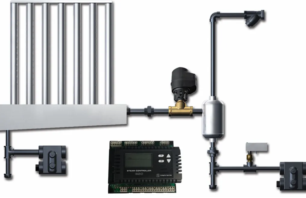
Steam Line Design
The steam line from device to distribution manifold is a critical performance element. Wrong material, slope, insulation or condensate drainage causes water build-up in the line, water hammer, capacity loss and uneven nozzle performance at the manifold.
Correct material: stainless steel (AISI 304 or 316), CPVC, or high-temp silicone hose (per device documentation). Length should be as short as possible (device-manifold <4 m), minimum 5% slope, full-length insulation, condensate trap at the low point.
| Item | Design Rule | If Wrong |
|---|---|---|
| Line length | < 4 m preferred; < 6 m maximum | 5-10% condensate loss |
| Slope | Minimum 5% from manifold to device | Water build-up → water hammer |
| Insulation | Min. 19 mm elastomeric along line | Condensation along line |
| Condensate trap | At low point, drain side | Manifold drips into duct |
| Material | Stainless / CPVC / silicone (per device) | PVC deformation, gasket leaks |
| Diameter | Per manufacturer table (flow-based) | Pressure drop, capacity loss |
Condensate Management
Condensate forming along the steam line collects at low points and must be drained. A condensate trap (T-fitting + siphon) sits at the low point; downstream of the trap, hot-water drain piping (CPVC, not PVC) is required.
Condensate is thermally sterile (water passed through 100°C); however, during draining it cools and microbial growth restarts. The drain line must be closed-system; air gap is mandatory.
Drain Slope
The drain line slope enables flow by gravity; insufficient slope causes water build-up, odour and backflow. Minimum 2% slope is recommended; for long lines, 3-4%. Minimise elbows; every elbow is pressure loss and a build-up risk.
Hot drain water (>80°C) exceeds PVC's glass-transition temperature and deforms it. Use CPVC, stainless or high-temperature polypropylene only. Drain pipe diameter must not be smaller than the device's drain port.
Manifold-Drain Link
Condensate inside a steam manifold (e.g. the SKD family) must be drained from the manifold base; otherwise water collects in the manifold and droplets are carried into the duct from the nozzle outlets. Correct design: drain port at the manifold base + hot-water-compatible line + air gap.
In facility-steam-fed systems (such as the SKD family), condensate volume can be high; drain sizing must follow device documentation. In hygienic sites, manifold + drain belong together in the annual cleaning protocol.
Pre-Design Checklist
The following 16-item checklist is a validation tool that takes 30 min at the design desk and cuts on-site mistakes by ~80%. The list can be used either as a brief for a new project or as an audit guide for an existing site.
| # | Check Item |
|---|---|
| 1 | Airflow (m³/h) (design and simultaneity values |
| 2 | Fresh-air ratio (%)) winter / summer delta profile |
| 3 | Target relative humidity (% RH) and tolerance band (±) |
| 4 | Indoor design temperature (°C), winter / summer |
| 5 | Water analysis (conductivity, hardness, TDS, chloride, silica, alkalinity) |
| 6 | Device type selection (steam / atomisation / evaporative) |
| 7 | Capacity calculation (kg/h) (including 15-20% safety margin |
| 8 | Modulation range (turndown ratio)) minimum 1:10 |
| 9 | Sensor point (room / duct / supply / process) |
| 10 | High-limit sensor location and setpoint (%) |
| 11 | Steam manifold location and nozzle pattern |
| 12 | Absorption distance (m), downstream obstruction check |
| 13 | Drain line (slope, air gap, material, siphon) |
| 14 | Maintenance access (front / side / top clearances) |
| 15 | BMS-automation integration (protocol, alarm points, trend log) |
| 16 | Commissioning + validation + sensor-calibration programme |
NKT Approach
NKT Nem Kontrol Teknolojileri, the official Turkish distributor of the Neptronic product family, runs an end-to-end engineering process. The NKT project flow has six stages: (1) site analysis, (2) water-sample analysis, (3) psychrometric capacity calculation, (4) device selection + TCO, (5) commissioning + PID tuning + BMS integration, (6) validation.
NKT's catalogue covers SKVF (evaporative cooler), SKH (high-pressure atomisation), SKV (evaporative humidifier) and SKD (direct steam injection); for resistive steam, the Neptronic SKE4 family is offered. Each of the 10 mistakes in this guide is caught early in the NKT process and corrected at the design desk.
Humidifier selection is a far wider engineering decision than a kg/h match. Sensor placement, PID control choice, absorption distance, drain design, water-treatment matching and BMS integration, these six axes determine long-term performance. The 10 mistakes in this guide account for 80% of post-commissioning service-call records; each is cheap to prevent at the design table and expensive to fix in the field.
The right device is the device chosen from the right technology family and supported by correct design decisions. The NKT engineering approach addresses these six axes at the start of every project; the 16-item checklist is co-completed with the customer at the proposal stage, and a validation report is delivered after commissioning. The result: a humidification system in which surprise service-call records approach zero.