During winter, the indoor air of buildings becomes noticeably dry. The reason is not a complex chemical process but a simple psychrometric reality: cold outdoor air carries very little water vapor; once this air enters a building and is heated, its relative humidity (RH) drops rapidly to inadequate levels such as 15–25%. This causes serious problems for both comfort and many industrial processes, paper curl in print rooms, static electricity outbreaks in textiles, mucosal dryness in hospitals, wood cracking in museums, and ESD risk in data centers being among the most common. For this reason, humidification load calculation is the fundamental step in correct equipment sizing. This guide walks through the three main inputs (design condition, outdoor air, and air volume) and provides concrete calculation examples using climate data for five major Turkish cities (Ankara, İstanbul, İzmir, Erzurum, Gaziantep). With NKT, Nem Kontrol Teknolojileri engineering perspective, the article harmonises ASHRAE Table 4 and TS 825 design conditions into a directly field-applicable approach.
Psychrometric Fundamentals: Relative Humidity, Absolute Humidity, and Dew Point
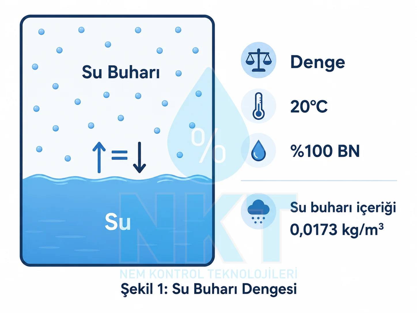
At the heart of humidification load calculation lies the fact that the water vapor carrying capacity of air varies with temperature. When air reaches the maximum amount of water vapor it can hold at a given temperature, it reaches its saturation point and relative humidity (RH) rises to 100%. This corresponds to the partial pressure of water vapor being equal to the saturation vapor pressure at that temperature. As air temperature increases, saturation vapor pressure grows exponentially; in other words, warm air can carry far more water vapor than cold air. This phenomenon is the primary cause of indoor air drying out in winter.
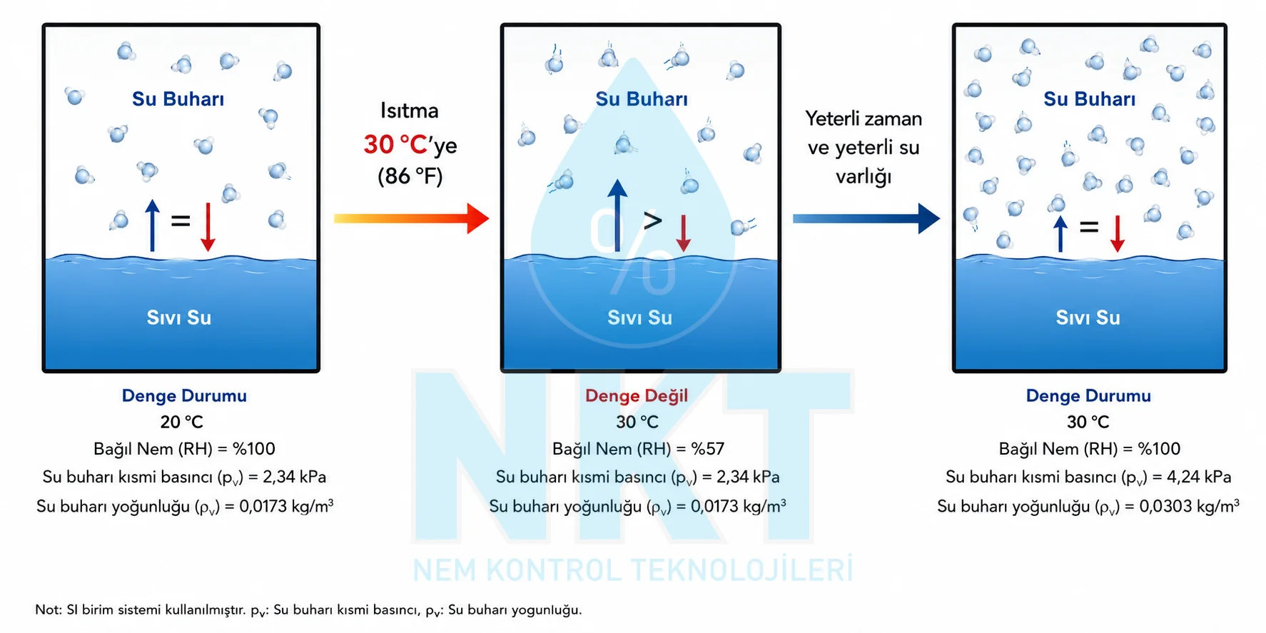
Let us illustrate with a practical example. One cubic meter of air at 20°C and 100% RH contains approximately 17.3 g of water vapor. If this air is heated to 30°C through a heating coil or battery (while the water vapor mass stays constant) the air's vapor-holding capacity rises to 30.4 g/m³, so relative humidity falls to about 57%. Absolute humidity (actual vapor content) has not changed; only the capacity changed. The same logic operates when winter outdoor air enters a building and is heated: outdoor air at -5°C / 80% RH (absolute humidity ≈ 2 g/kg) heated to 22°C indoors drops to approximately 12% RH. This gap is the source of the humidification load.
Dew point is the temperature at which water vapor in the air begins to condense. Equivalently, it is the temperature at which the existing water vapor content corresponds to 100% RH. Dew point is an absolute humidity indicator: even when air is heated or cooled (without condensation), its dew point does not change. Therefore, when analyzing outdoor air conditions, using dew point or absolute humidity (g/kg or g/m³) instead of relative humidity provides a much more reliable calculation basis. In cold regions like Erzurum, outdoor air dew point is around -25°C; this corresponds to an absolute humidity content of approximately 0.4 g/kg, so when targeting an indoor condition of 22°C / 40% RH (absolute humidity ≈ 6.5 g/kg), the moisture that must be added is 15 times the outdoor content.
These three concepts (relative humidity, absolute humidity, and dew point) are tightly interrelated and graphically connected on a psychrometric chart. For a detailed visual examination, see our psychrometric chart glossary entry. Humidification load calculation generally uses absolute humidity (g water vapor / m³ dry air, or g/kg dry air) because it is a mass-based quantity that directly answers the question "How many kg of water must I add per hour?"
What Is Humidification Load and Why Calculate It?
Humidification load is the amount of water vapor that must be added to a space, typically over one hour or one minute. In the metric system it is expressed in kg/hr or g/hr; in the imperial system as lb/hr. The load is calculated by multiplying the difference between the target indoor absolute humidity content (B) and the existing outdoor or mixed-air absolute humidity content (D) by the air volume entering the space (V):
L (kg/hr) = (B − D) × V
// Where:
B = Indoor design absolute humidity (kg water / m³ dry air)
D = Outdoor air absolute humidity (kg water / m³ dry air)
V = Air volume entering the space per minute or hour (m³/hr)
Performing this calculation correctly yields two main benefits. First, correct equipment sizing: a humidifier sized below the calculated load will never reach the target RH indoors and will run continuously at full capacity, shortening its life; conversely, an oversized device cycles frequently under light load (short cycling), control accuracy degrades, and condensation risk rises. Second, upfront prediction of energy and water consumption: producing 1 kg of steam requires about 0.75 kWh of electricity (for a resistive steam humidifier) plus 1 liter of water and additional regeneration losses; the annual energy budget can only be estimated when the load is calculated correctly.
1) Design condition — Target temperature and relative humidity (ASHRAE Table 4 or process requirement).
2) Outdoor air design condition — ASHRAE 99% dry-bulb + driest-month average RH (or TS 825 winter design temperature).
3) Air volume — Outdoor airflow entering the space depending on the system type (natural ventilation, mixed air, makeup, or exhaust).
Misjudging any one of these three inputs can shift the calculated load by ±30–50%. Air volume estimation is the most common source of field errors: there is often a 20–40% discrepancy between design-based ACH (air changes per hour) and actually measured ACH. NKT, Nem Kontrol Teknolojileri engineers adopt the standard practice of validating design calculations with real field measurements (building pressure test, fresh air measurement, return air measurement).
Design Conditions (Set Point Selection)
The first input of humidification load calculation is the temperature and relative humidity combination targeted indoors. These values are determined by process requirements, human comfort, or material stabilization needs. ASHRAE Table 4 (Application Handbook) recommends reference set points for typical industry and application areas. The table below lists practical design conditions for the applications most frequently encountered in Turkish industry.
| Sector / Process | Temperature (°C) | Relative Humidity (% RH) |
|---|---|---|
| Textile — Cotton Weaving | 24 | 60–65 |
| Textile — Cotton Combing | 22 | 50–60 |
| Textile — Synthetic Yarn Processing | 22 | 50–55 |
| Lithographic Print Room | 24 | 45 |
| Web Offset / Paper Storage | 24 | 50 |
| Hospital — Operating Room | 20–22 | 50 |
| Hospital — Neonatal / NICU | 22–24 | 50 |
| Museum, Archive, Library | 21–22 | 50–55 |
| Data Center / Computer Room | 22–24 | 40–50 |
| Tobacco / Cigarette Processing | 24 | 60–70 |
| Wood Working / Furniture Workshop | 20 | 40–45 |
| Comfort (Office / Residential) | 21–22 | 30–45 |
When selecting a set point, do not consider only the process requirement; surface condensation risk must also be taken into account. If indoor dew point exceeds the temperature of the coldest surface in the building envelope (typically window glass or a thermal-bridge concrete detail), problems such as sweating, mould, and wood rot occur. For this reason, high RH targets (e.g. above 60% RH) require strong insulation and low U-value windows. For a Konya print room, 45% RH is generally a safe limit; for a Bursa textile plant targeting 60% RH, windows should at minimum be double-glazed with low-emission coating, and wall insulation should exceed the TS 825 Zone 2 climate requirements.
For museums and archives, the ASHRAE Class A / B / C / D classification serves as a guide: stable protection within a ±5% RH bandwidth is required for Class A collections, while ±10% RH is sufficient for temporary exhibition areas. For hospital operating rooms, ASHRAE 170 permits a 20–60% RH range; however, most Turkish hospital designs prefer a 50% RH set point, this is a balanced point both for patient comfort and electrosurgical spark risk.
Türkiye Climate Data: Outdoor Air Design Conditions
Humidification load calculation is performed under the driest and coldest conditions of the year. This is a "worst case" approach and guarantees that the device can sustain the target RH throughout the year under any weather condition. In practice, the 99% (or sometimes 99.6%) dry-bulb temperature from ASHRAE Climatic Design Conditions tables is combined with the driest-month average relative humidity. TS 825 defines four main climate zones for Türkiye; combined with ASHRAE data, the table below is obtained.
| City | Climate Zone (TS 825) | Winter Design Temp. (°C) | Average Winter RH (%) | Absolute Humidity (g/kg) |
|---|---|---|---|---|
| Ankara | 3 | -10 | 75 | 1.3 |
| İstanbul | 2 | -3 | 78 | 2.4 |
| İzmir | 1 | 0 | 70 | 2.7 |
| Erzurum | 4 | -23 | 73 | 0.4 |
| Gaziantep | 3 | -6 | 71 | 1.9 |
| Konya | 3 | -10 | 72 | 1.3 |
| Bursa | 2 | -3 | 76 | 2.4 |
| Kayseri | 4 | -15 | 74 | 0.8 |
Note: The values above are approximate design figures based on ASHRAE Climatic Design Conditions and TS 825 references. For detailed site calculations, meteorology station records or MGM (Turkish State Meteorological Service) long-term averages should be used.
The numbers in the table reveal one key feature: although the relative humidity of outdoor air may appear high, the absolute humidity (g/kg) is very low. Winter air in Erzurum may have 73% RH; however, at -23°C this corresponds to only 0.4 g water vapor per kg of dry air. For comparison, a 22°C / 50% RH indoor space carries about 8.3 g/kg; meaning Erzurum's outdoor air is 20 times drier than the indoor target. This raises the humidification load critically.
From a climate-zone perspective: coastal cities like İstanbul, İzmir, and Antalya require the lowest load, because outdoor air is both relatively mild and has a high absolute humidity content. Central Anatolia (Ankara, Konya, Kayseri) produces moderate loads. Eastern Anatolia (Erzurum, Kars, Ağrı) hosts Türkiye's highest load demands; for these regions, it has become an engineering standard to leave an additional 30–40% margin when sizing humidifiers. South-Eastern Anatolia (Gaziantep, Şanlıurfa, Diyarbakır) records low absolute humidity values throughout the year due to its dry continental climate; outdoor air absolute humidity fluctuates between 1–2 g/kg in the winter-to-spring transition months in particular.
Indoor Air Volume and Ventilation Systems
The third (and the most variable in the field) input of humidification load calculation is how much outdoor (dry) air enters the space per hour. This value is assessed in four main types depending on the ventilation system architecture: natural ventilation (infiltration), mixed-air system, makeup (all-fresh-air) system, and exhaust-balanced system.
Natural Ventilation: Infiltration
In natural ventilation, uncontrolled air leakage (infiltration) is involved; outdoor air enters through cracks in the building envelope, window joints, under-door gaps, and roof details. The annual average infiltration rate is expressed in ACH (Air Changes per Hour) depending on the building's structural tightness class. For a modern, well-insulated industrial building, 0.3–0.6 ACH is typical, while values of 1.0–2.5 ACH can be reached in older structures.
| Building Tightness Class | Typical ACH | Example Applications |
|---|---|---|
| Tight | 0.3 | New construction, air barrier, double-sealed windows |
| Average | 0.6 | Standard industrial building, single-story, wood/PVC window |
| Poor | 1.0 | Older structure, industrial building with insulation deficits |
| Very Leaky | 2.5 | Heavy in/out traffic, frequently opened large doors (warehouse, packaging) |
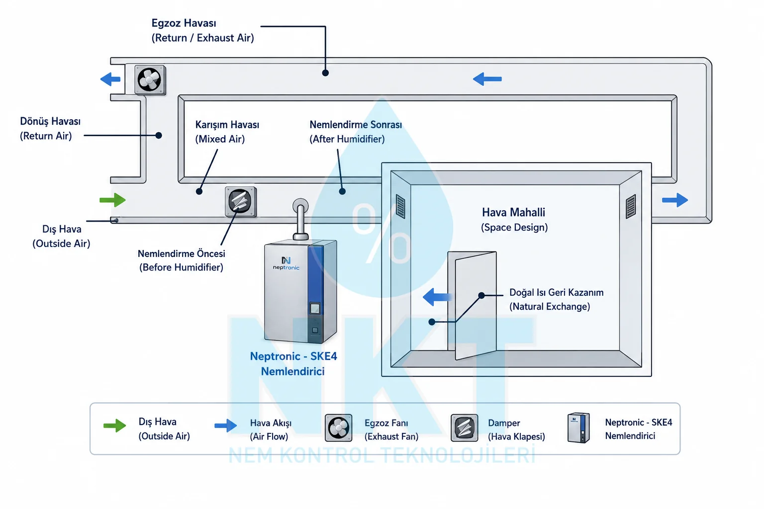
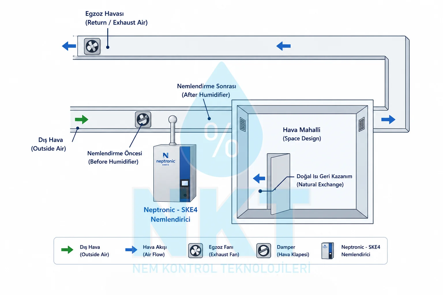
Mixed Air System
Most modern HVAC systems operate on the mixed-air principle: air returning from the indoor space (return air) is combined with fresh outdoor air in a mixing box, conditioned for temperature and humidity, then supplied back to the space. Typical mixing ratios are 80–90% return + 10–20% fresh air. The critical quantity for humidification load calculation in this system is the fresh-air component's flow rate, the return air is already at the indoor humidity level and requires no additional humidification. Because the building is kept under positive pressure, there is no infiltration through the envelope (instead, excess air leaks out); the fresh-air flow to be considered is limited only by the makeup ratio.
Makeup Air System (100% Fresh Air)
Some applications cannot reuse return air: in conditions of hygienic necessity (operating rooms, pharma, food preparation), contamination risk (chemical processes, welding workshops), and odor/smoke generation (kitchens, paint booths), 100% fresh air (makeup air) is mandatory. In this system, all supply air is drawn from outside and exhausted at the same rate. The humidification load is calculated directly from the total supply flow rate and ends up 5–10 times higher than in a mixed-air system.
Exhaust-Balanced (Exhaust-Driven) System
In some industrial buildings (printing, textiles, welding workshops), a fixed exhaust volume runs continuously, process exhaust, local hoods, WC and kitchen exhausts. Outdoor air enters in an amount equal to this exhaust volume; a "makeup air handler" (compensation air fan) controls the inlet. The calculation approach is the same as for a makeup system: outdoor air at the exhaust flow rate is humidified. If the exhaust fan creates negative indoor pressure, structural infiltration also kicks in and the load increases; therefore, it is recommended that the building be kept slightly positive (+5 to +15 Pa) by design.
Case Study 1: Lithographic Press Room in Konya (Natural Ventilation)
A medium-sized lithographic print plant in Konya is experiencing paper curl and color shift (mis-registration) problems during winter months. The source of the issue is low indoor relative humidity: measurements show 22% RH in the press hall. Design target: 24°C / 45% RH. Room dimensions: 30 m × 18 m × 3 m (height). Structural class: average (0.6 ACH). Ventilation type: natural, no mechanical supply, infiltration enters from outdoors.
Step-by-Step Calculation
Indoor design condition is 24°C / 45% RH, and Konya winter design outdoor is -10°C / 75% RH. Absolute humidity values are taken from standard psychrometric tables (saturated 24°C = 0.0218 kg/m³; saturated -10°C = 0.00218 kg/m³).
A = 0.0218 kg/m³
// 2. Actual absolute humidity at design condition (24°C / 45% RH)
B = A × 45 / 100 = 0.0218 × 0.45
B = 0.00981 kg/m³
// 3. Saturated absolute humidity at outdoor temperature (-10°C)
C = 0.00218 kg/m³
// 4. Actual absolute humidity of outdoor air (-10°C / 75% RH)
D = C × 75 / 100 = 0.00218 × 0.75
D = 0.001635 kg/m³
// 5. Absolute humidity difference (moisture to add)
E = B − D = 0.00981 − 0.001635
E = 0.008175 kg/m³
// 6. Room volume
V = 30 × 18 × 3
V = 1,620 m³
// 7. Hourly infiltration volume (0.6 ACH)
V_inf = V × 0.6 = 1,620 × 0.6
V_inf = 972 m³/hr
// 8. HUMIDIFICATION LOAD
L = E × V_inf = 0.008175 × 972
L ≈ 7.95 kg/hr ≈ 8 kg/hr
The calculated 8 kg/hr load is typical for a small-to-medium lithographic press room. Konya's inland Anatolian climate keeps outdoor air absolute humidity very low (1.3 g/kg), which raises the calculation. If the same room were located in İstanbul (-3°C / 78% RH outdoor), the load would drop to approximately 6.5 kg/hr; in Erzurum (-23°C / 73% RH), it would rise to 9.2 kg/hr.
Equipment Recommendation: Neptronic SKE4
For the calculated 8 kg/hr load, a 10 kg/hr device is selected by adding a 20% service margin. Neptronic SKE4-10 is an ideal alternative for this capacity: resistive steam humidifier technology, water-quality independence (compatible with DI, RO, or hard mains water), ±1% RH control accuracy, stainless steel evaporation chamber, and BMS integration over BACnet/Modbus.
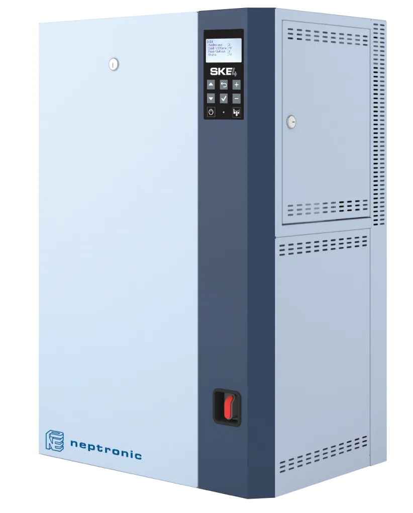
In the device distribution piping design, insulated stainless steel steam ducts must be used to prevent steam from condensing before reaching the press hall. In high-altitude cities like Konya (≈1,020 m), low atmospheric pressure slightly affects steam generation efficiency; on this point, Neptronic SKE4 devices' automatic pressure compensation feature eliminates the need for additional adjustment.
Case Study 2: Cotton Combing Textile Plant in Bursa (Mixed Air)
A medium-to-large cotton yarn plant operating in Bursa İnegöl OSB experiences fiber breakage and static-electricity-induced downtime in its combing department. The root cause of fiber breakage is low RH: 38% RH on average is being measured. Design target: 22°C / 60% RH (optimal for cotton combing). Hall dimensions: 60 m × 30 m × 4 m (height 4 m, due to machine height). The building is structurally well-sealed, has a mixed air system, and 20% makeup ratio. AHU return flow rate is 25,000 m³/hr.
Step-by-Step Calculation
Indoor design condition is 22°C / 60% RH, and Bursa winter design outdoor is -3°C / 78% RH.
A = 0.0194 kg/m³
// 2. Actual absolute humidity at design condition (22°C / 60% RH)
B = A × 60 / 100 = 0.0194 × 0.60
B = 0.01164 kg/m³
// 3. Saturated absolute humidity at outdoor temperature (-3°C)
C = 0.00385 kg/m³
// 4. Actual absolute humidity of outdoor air (-3°C / 78% RH)
D = C × 78 / 100 = 0.00385 × 0.78
D = 0.003003 kg/m³
// 5. Absolute humidity difference (moisture to add)
E = B − D = 0.01164 − 0.003003
E = 0.008637 kg/m³
// 6. Total AHU return flow rate
V_total = 25,000 m³/hr
// 7. Fresh-air component (20% makeup)
V_inc = V_total × 0.20
V_inc = 5,000 m³/hr
// 8. HUMIDIFICATION LOAD
L = E × V_inc = 0.008637 × 5,000
L ≈ 43.2 kg/hr ≈ 45 kg/hr
The calculated 45 kg/hr load is typical for a medium-to-large textile line. Bursa's Marmara climate keeps outdoor air absolute humidity relatively high (2.4 g/kg); nevertheless, the high RH target (60%) combined with a large total air volume pushes the load to 45 kg/hr. If the same plant were located in Erzurum, the load would rise to approximately 60–65 kg/hr.
Equipment Recommendation: Neptronic SKS4
For the 45 kg/hr load, a 50 kg/hr device is selected with a 15–20% margin. Because the textile plant operates in integration with an existing steam boiler system, Neptronic SKS4-50 (steam-to-steam type) is recommended: it uses process steam to produce sterile, mineral-free clean steam; the scale management system extends maintenance intervals; and it operates independently of boiler water quality.
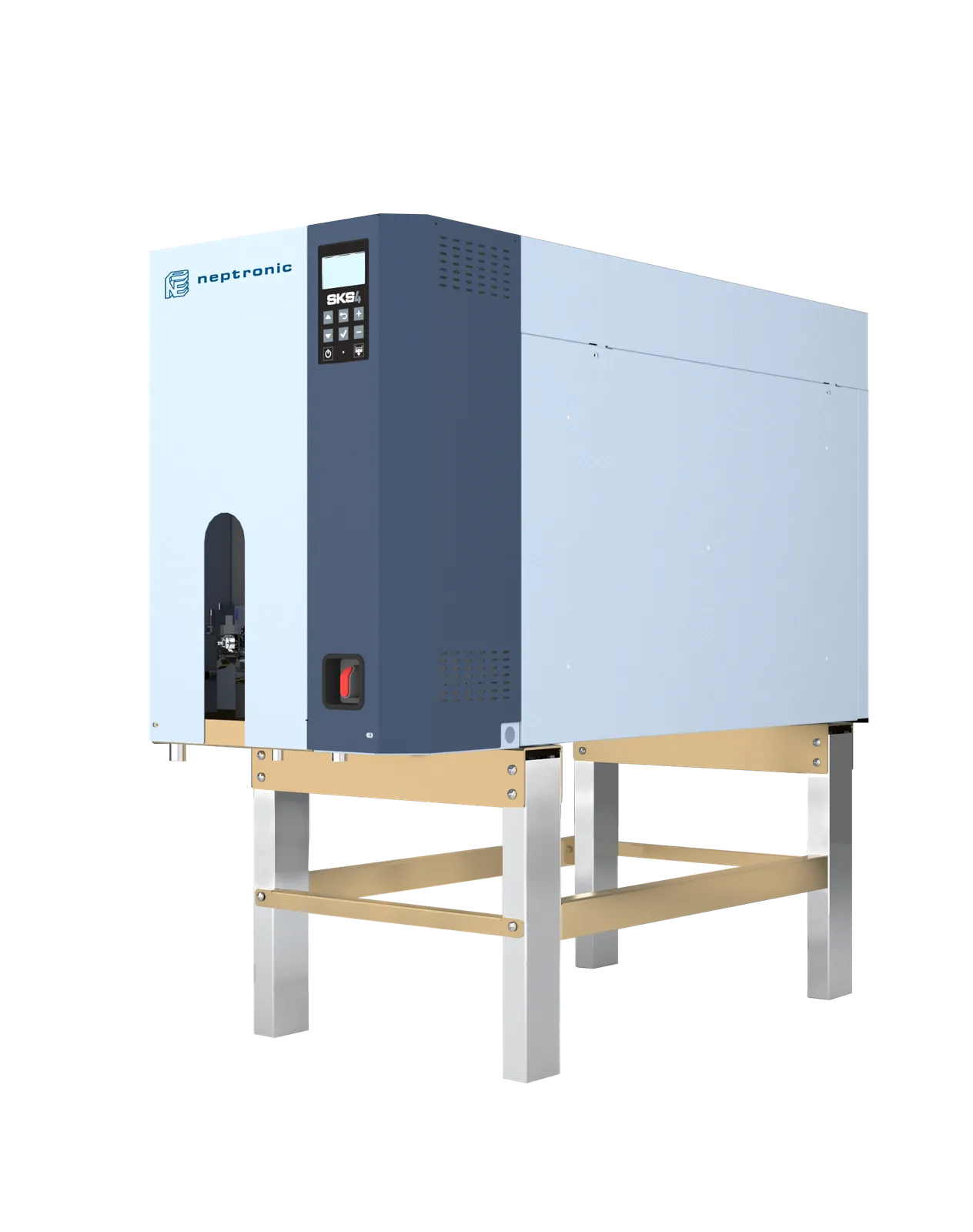
For textile applications, options for steam distribution include direct overhead supply or a steam manifold (steam grid) within the AHU. When direct supply over the combing machines is used, a minimum 2 m clearance and steam distribution pipe insulation are mandatory to prevent steam droplets from landing on fiber surfaces. NKT engineering teams verify steam distribution on-site with airflow pattern (CFD or smoke tests) and, in observed problem areas, may recommend manifold extension or multiple distribution pipes.
Economizer Cycle and Its Effect on Humidification Load
The economizer cycle is a control strategy used in modern AHUs to obtain free cooling. When outdoor air temperature falls below the return-air temperature from the space, the AHU dampers switch to 100% fresh-air mode and the space is cooled without operating mechanical cooling. This mode is most active during spring and autumn shoulder seasons and on cool nights; it can reduce annual cooling energy consumption by 15–30%.
The economizer mode's effect on humidification load is dramatic: when AHU dampers switch to 100% fresh-air mode, the mixing ratio disappears and the V_inc term in the load calculation equals the entire AHU flow rate. In the Konya print room example, this leads to:
V_inc = 15,000 × 0.15 = 2,250 m³/hr
// Load = 0.008175 × 2,250 ≈ 18 kg/hr
// Economizer-ON mode (100% makeup)
V_inc = 15,000 m³/hr
// Load = 0.008175 × 15,000
L ≈ 122 kg/hr (approx. 7× increase)
This situation is critical from a design standpoint: equipment sizing for economizer-active AHUs must always be based on the peak economizer-on load; otherwise, the RH set point falls significantly during shoulder seasons. The 12-month load profile is summarised in the table below:
| Month | Avg. Outdoor Temp. (°C) | Avg. Outdoor RH (%) | Typical Makeup Air (%) | Humidification Load (kg/hr) |
|---|---|---|---|---|
| January | -3 | 78 | 100 (economizer) | 110 |
| February | -1 | 76 | 100 (economizer) | 95 |
| March | 5 | 68 | 80 | 62 |
| April | 11 | 62 | 50 | 32 |
| May | 16 | 60 | 20 | 10 |
| June | 20 | 58 | 15 | 4 |
| July | 23 | 55 | 15 | 0 |
| August | 23 | 56 | 15 | 0 |
| September | 18 | 60 | 20 | 7 |
| October | 12 | 65 | 40 | 26 |
| November | 5 | 72 | 80 | 58 |
| December | -2 | 77 | 100 (economizer) | 100 |
As can be seen, the annual peak load occurs in January in economizer-on mode (~110 kg/hr). Equipment selection should be based on this value, with a 15–20% margin pointing to a 130 kg/hr nominal humidifier. For the example Konya print room, an economizer-active design recommends an SKE4-130 (or 2 × SKE4-65 redundant) instead of an SKE4-100.
Equipment Selection and Sizing
Once the humidification load is calculated, equipment selection is made across 5 main criteria: capacity (load + margin), steam generation technology (resistive, electrode, gas-fired, atomization, steam-to-steam), control accuracy, water quality requirements, and hygienic requirements. Each criterion highlights a different Neptronic product family.
Criterion 1: Capacity and Margin
A 15–25% service margin is added to the calculated theoretical load. This margin serves several purposes: (a) bringing the space from empty state to target RH at startup (start-up load is much higher than steady-state load; the device typically runs at full capacity for 2–3 hours), (b) compensating for capacity loss over time from dirty heaters or calcium buildup, (c) reserve for unforeseen additional moisture losses (door openings, crowded personnel, process exhaust). The margin should not exceed 25%; oversizing produces short cycling and poor control quality.
Criterion 2: Water Quality and Steam Generation Technology
In many regions of Türkiye, mains water hardness is high (Konya, Kayseri, Eskişehir, Şanlıurfa). This directly affects device technology choice. As detailed in our electrode vs. resistive humidifier comparison guide, electrode-cylinder humidifiers generate steam by directly using the water's electrical conductivity; therefore hard mains water is mandatory. They cannot operate with soft water (DI/RO). In contrast, resistive (Neptronic SKE4) devices operate via heat-based elements and are compatible with any type of water (DI, RO, demineralized, or hard mains). This is a critical advantage in pharma, food, and hospital applications.
| Sector / Requirement | Recommended Neptronic Model | Typical Capacity | Water Quality |
|---|---|---|---|
| General office / comfort | SKE4 (Resistive) | 2.7–30 kg/hr | Mains water |
| Printing / Lithographic | SKE4 (Resistive) | 10–50 kg/hr | Mains + softener |
| Textile (mid-size) | SKE4 or SKS4 | 30–120 kg/hr | Mains + softener |
| Textile (large, existing steam) | SKS4 (Steam-to-Steam) | 100–570 kg/hr | Existing process steam |
| Hospital / Operating Room | SKS4 (Hygienic) | 20–80 kg/hr | DI / RO or clean steam |
| Pharmaceutical | SKS4 (Sterile) | 50–200 kg/hr | DI / RO + USP grade |
| Data Center | SKE4 (Resistive) | 15–60 kg/hr | Mains + DI |
| Large industrial (high capacity) | SKG4 (Gas-Fired) | 50–400 kg/hr | Mains |
| Museum / Archive (sensitive) | SKE4 (±1% RH) | 5–30 kg/hr | DI / RO |
| Cold Storage / Low Temperature | SKH (Atomization) | Variable | RO |
Criterion 3: Control Accuracy
For applications requiring sensitive RH control (printing ±2% RH, museum ±5% RH, pharma ±3% RH), the resistive SKE4 / SKS4 models should be preferred. Electrode-cylinder systems typically operate in a ±5% RH band; acceptable for most comfort applications but inadequate for process applications. Control modulation is also critical: SCR (Silicon Controlled Rectifier) based modulating control offers 5–10× tighter RH tracking compared with on/off relay control.
Criterion 4: Single Device or Multiple (N+1 Redundant)?
For a 50 kg/hr load there are two choices: 1 × SKE4-50 (single cabinet, modular) or 2 × SKE4-25 redundant. The single device requires lower investment and less floor area; two devices provide N+1 redundancy (when one device is taken offline for maintenance, the other continues). N+1 is standard practice in critical applications (hospital, pharma, data center). The modular SKE4 family combines the advantages of both approaches by offering multiple independent cylinder configurations within a single cabinet.
NKT Engineering Services and Rapid Calculation Tools
NKT, Nem Kontrol Teknolojileri is one of the leading institutions in humidity-control engineering in Türkiye. Through our technology partnership with Neptronic (Canada (industrial steam humidifier manufacturer), NKT delivers full-package services) from feasibility studies and commissioning to post-commissioning performance validation and periodic maintenance, for print rooms, textile plants, hospitals, museums, pharmaceutical factories, and data centers.
NKT Engineering Services
- Site Analysis and Measurement: Building pressure test, blower-door test, CO₂ tracking, recording of existing RH and temperature profiles, derivation of real ACH and leakage map.
- Psychrometric Calculation and System Design: Detailed load calculation referenced to ASHRAE Table 4 and TS 825, equipment sizing, control-strategy design.
- Equipment Selection and Supply: Selection of the most suitable configuration from the Neptronic SKE4, SKS4, SKG4, SKH product family; local stock and fast delivery.
- Commissioning and Performance Validation: On-site PV tests, RH/temperature logger measurements, control parameter optimization.
- Periodic Maintenance and 24/7 Service: A field engineer network across every region of Türkiye, spare-parts inventory, remote monitoring.
Rapid Calculation Tools
Instead of working through every formula in this guide by hand, you can calculate in seconds with NKT's free web-based engineering tools:
- Psychrometric Calculator — Outputs dew point, absolute humidity, enthalpy, wet-bulb, vapor pressure, and specific volume from temperature + relative humidity inputs.
- Air Mixing Calculator — Instantly calculate the mixing condition (temperature + humidity) of return air + fresh air.
- Humidification Load Calculator — Interactive tool that runs the formula described in this guide and returns kg/hr output directly.
- NKT Pro mobile app — On-site device selection, load calculation, and customer-ready report generation; available for iOS and Android.
Humidification load calculation, when applied correctly, eliminates equipment selection errors, makes the energy budget predictable, and ensures process quality continuity. The three main inputs described in this guide (design condition, outdoor air, air volume) combined with the psychrometric table data establish a calculation discipline applicable in all climate zones of Türkiye. NKT, Nem Kontrol Teknolojileri adopts this discipline as a standard practice in its corporate project partnerships; the engineering team prepares an independent psychrometric analysis report for every site.
For more information, you can contact us via the contact page; and visit the NKT Akademi homepage for our other guides on psychrometrics and humidity control.