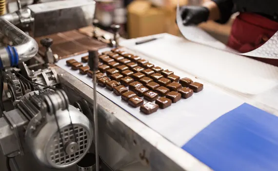
Chocolate and confectionery production stands among the most thermodynamically demanding processes in modern food engineering. The crystalline structure of cocoa butter, the surface activity of sugar, and the gloss of enrobed products all rest upon delicate balances that can collapse within a few degrees of temperature or a few grams of moisture. Cooling tunnels sit at the heart of this fragile equilibrium: this is where post-tempering cocoa butter sets in its Beta-V crystalline form, where panned product surfaces acquire their gloss, and where enrobed chocolates become packaging-ready. Yet most producers overlook a critical truth, the success of this stage depends as much on, sometimes more than, airborne moisture management as it does on refrigeration capacity.
At the cooling tunnel entrance, warm product meets cold air. If the absolute humidity of that air (in g/kg of dry air) implies a dew point above the product surface temperature, the chocolate surface instantly becomes a condensation surface. This few-second moisture deposition forms a microscopic water film, but its visual consequences are permanent: the surface goes matte, gloss is lost, grey-white sugar bloom appears, and the product either loses sales value or is scrapped entirely. This article addresses cooling tunnel dehumidification engineering from a comprehensive perspective, psychrometric fundamentals, an enrobed chocolate case study, the correct selection and integration logic for silica-gel rotor desiccant systems, and the field-proven technical solutions delivered by NKT, Nem Kontrol Teknolojileri.
Bloom on Chocolate Surfaces: Origins of Fat and Sugar Defects
The white, grey or matte appearance occasionally visible on chocolate surfaces is the quality defect known industry-wide as bloom. Consumers often interpret this as "staleness", yet bloom is not a microbiological issue but a purely physicochemical surface phenomenon. Two principal bloom mechanisms are recognised in academic literature, and both are directly linked to the cooling tunnel stage.
Sugar Bloom: Directly Moisture-Driven
Sugar bloom forms when sucrose crystals on the chocolate surface come into contact with surface moisture. The mechanism unfolds step by step: in a high-humidity environment or due to condensation at the cooling tunnel inlet, a thin water film settles on the chocolate surface; in this film the surface sugar crystals dissolve and a saturated sugar solution forms; when the water subsequently evaporates, the dissolved sugar recrystallises, not in its original form but as much larger, disordered crystals. These new crystals scatter light, dulling the chocolate surface and producing the characteristic white layer. The flavour may not change, but visual acceptability is entirely lost.
The critical trigger for sugar bloom is the dew-point differential at the tunnel inlet. When warm product (for example enrobed chocolate at ~28-30°C) meets cold tunnel air (~0-10°C), condensation is unavoidable if the tunnel-air dew point lies above the product surface temperature. For this reason, academic sources and industry best practice both specify a maximum 50% RH and a preferred 35-45% RH at the cooling tunnel inlet. At these levels the tunnel-air dew point stays sufficiently low to make surface condensation physically impossible.
Fat Bloom: Temperature-Fluctuation Driven
Fat bloom originates from instability in the cocoa butter crystalline structure. Cocoa butter exhibits six polymorphic forms (Form I-VI); the glossy, hard, brittle texture of high-quality chocolate is achieved only through Form V (Beta-V) crystals. The tempering process seeks to maximise Form V nucleation in the chocolate mass. The cooling tunnel is the critical stage where this structure is locked in.
If the product surface temperature falls too rapidly inside the tunnel, or if temperature fluctuations occur along its length, cocoa butter shifts to an unstable polymorph such as Form IV; over time, this form converts to the lower-energy Form VI and during this transition liquid fat migrates to the surface, producing the whitish, oily layer. Unlike sugar bloom, fat bloom is moisture's indirect effect: humidity fluctuation inside the tunnel increases evaporator defrost demands, disrupts temperature homogeneity, and raises fat bloom risk.
Surface Defects in Confectionery and Panned Products
Bloom is not exclusive to tablet and enrobed chocolates. Panned (drage) products, hard candy, caramels, jellies, and fondant-filled confectionery are equally sensitive to surface humidity. In panning, the polishing gloss layer remains stable only at 30-40% RH and 18-22°C; high humidity initiates surface crystallisation and syrup swelling. Hard candies subjected to surface humidity undergo rapid cold flow and tackiness, leading them to adhere directly to packaging and lose shelf life. For these reasons confectionery facilities must apply the same humidity discipline to the post-tunnel holding zone and the pre-packaging buffer zone as they do to the cooling tunnel itself.
Cooling Tunnel Types and Operating Principles
Industrial cooling tunnels are built in different configurations depending on product type, capacity requirement, and line geometry. Designing a dehumidification strategy demands a thorough analysis of the tunnel-specific airflow pattern, opening geometry, and evaporator placement. Three principal types are practically significant.
Linear (Straight-Path) Cooling Tunnels
Linear tunnels are the most widespread configuration, with the conveyor running in a straight line through the tunnel. They are favoured for enrobed chocolate lines, post-moulding tablet cooling, and after-panning drying. Typical lengths range from 10 to 50 metres; examples exceeding 80 metres exist for higher-throughput requirements. Two to four evaporator groups are placed along the conveyor, and airflow is generally counter-flow (against product direction); this ensures the product nearest the tunnel exit encounters the coldest air, securing the final temperature target.
The advantage of linear tunnels from a humidity-control perspective is the predictability and uniformity of the airflow pattern; the disadvantage is that both ends contain product-entry/exit openings, doubling the infiltration load. For chocolate, the typical tunnel temperature is 0-10°C and target RH is 40-50%.
Spiral (Helical) Cooling Tunnels
Spiral tunnels are designed to deliver long residence times within a small floor footprint. The conveyor wraps in a helical pattern around a vertical axis; product ascends or descends spirally while airflow circulates around all product surfaces. They are ideal for products requiring 30-60 minutes of cooling, particularly high-fat enrobed chocolates and filled pralines. Spiral tunnels have only one inlet and one outlet opening, making air-sealing management easier than in linear tunnels; however, the internal volume is much larger and evaporator defrost strategy becomes more complex.
Tunnel-less Cooling Cells and Batch Systems
For small-scale production and specialty items (artisan praline, seasonal packaged chocolate, special-batch production), enclosed cooling cells are used. Unlike tunnels, these systems do not provide continuous flow; trays are loaded, the door is closed, and cooling proceeds for a defined period. From a humidity perspective these systems are the easiest to control because there is no atmospheric mixing other than at door openings; however, each door opening introduces a concentrated moisture load to which the system must react quickly.
| Product Category | Tunnel Type | Internal Temp (°C) | Target RH (%) | Dew Point Target (°C) | Moisture Risk |
|---|---|---|---|---|---|
| Enrobed chocolate | Spiral / Linear | 8 – 14 | 40 – 50 | 0 – 4 | Very High |
| Tablet & moulded chocolate | Linear | 10 – 16 | 40 – 50 | 2 – 6 | High |
| Panned drage | Cell / Linear | 15 – 22 | 30 – 45 | 3 – 8 | High |
| Caramel & hard candy | Linear | 10 – 16 | 40 – 55 | 2 – 7 | High |
| Praline & filled | Spiral | 8 – 12 | 40 – 50 | 0 – 3 | Very High |
| Liquorice | Linear / Tunnel | 15 – 20 | 35 – 45 | 3 – 7 | High |
| Biscuit/cake cooling | Linear | 18 – 24 | 50 – 60 | 10 – 15 | Medium |
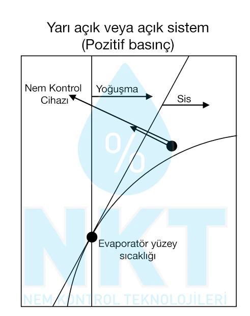
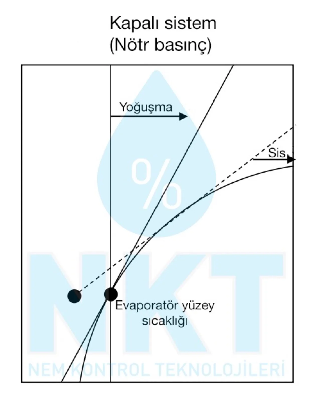
The Mechanics of Condensation at the Tunnel Inlet
The condensation problem at the cooling tunnel inlet rests on a simple observation: any surface cooled below its own dew point will condense water vapour out of the air. When a warm product (for example enrobed chocolate at 28°C surface temperature) reaches the tunnel inlet, the surrounding air suddenly meets a cold stream at 0-10°C. If the absolute humidity in this cold air corresponds to a dew point below the product surface temperature, nothing happens. However, if the air has not been dehumidified sufficiently, the chocolate surface lies below the air dew point and surface condensation begins instantly.
Several physics laws govern this process. First, the saturation pressure curve: air can hold a temperature-dependent maximum mass of water vapour; as temperature falls, this capacity decreases exponentially. At 30°C, air can carry ~27 g/kg; at 14°C, only ~10 g/kg. Second, absolute-humidity conservation: when a parcel of air is cooled, its absolute humidity content does not change, only its relative humidity rises. Air at 30°C and 60% RH (16 g/kg) cooled to 14°C still carries 16 g/kg, but its RH is now above 100% and the surplus deposits as condensation. Third, the local boundary-layer behaviour: a thin boundary layer forms between the product surface and the air, and condensation occurs there as a microscopic water film.
In practical engineering, the inequality must be reversed: the tunnel air's absolute humidity (w_air) must be lower than the saturation humidity at the product surface temperature (w_saturation). A safety margin of 3-5 g/kg is typically applied; for example, with an enrobed chocolate surface at 12°C, w_saturation ≈ 8.7 g/kg and the tunnel air should carry at most 4-5 g/kg absolute humidity; which corresponds to roughly +4°C dew point.
Infiltration: The Moisture Load Through Openings
The conveyor openings at the tunnel inlet and outlet are the principal pathways through which ambient air infiltrates the tunnel. In modern facilities, this infiltration accounts for 40-70% of the total moisture load. Infiltration load is proportional to opening area, indoor-outdoor absolute humidity difference, air density, and the conveyor-induced drag velocity.
Where A is opening area (m²), v is effective air velocity (m/s, typically 0.2-0.5), ρ is air density (≈1.2 kg/m³), w is absolute humidity (g/kg), and the result is the infiltration moisture load in g/hour. As a worked example: outdoor conditions of 30°C and 70% RH (≈19 g/kg), tunnel interior 12°C and 45% RH (≈4 g/kg), 0.5 m² opening, v = 0.3 m/s. Infiltration ≈ 9,700 g/h ≈ 233 L/day per opening. A single tunnel inlet opening carries an equivalent of roughly 230 litres of water per day in moisture load.
Target Dew Point and Psychrometric Analysis
The success of cooling tunnel humidity control begins with determining the correct dew-point target. Dew point is the temperature at which condensation begins when air is cooled, and it is the direct indicator of absolute humidity. Relative humidity (RH) alone can be misleading because it is temperature-dependent: the same 50% RH means 16 g/kg in summer at 30°C and 4 g/kg in winter at 10°C. In tunnel engineering, using dew point (rather than RH) is the safer reference.
The Product-Surface-Temperature vs Dew-Point Rule
The core rule reads: the dew point of the tunnel internal air must remain below the lowest surface temperature the product will encounter inside the cooling tunnel. This rule is applied with at least a 3°C safety margin. Practical values:
- Enrobed chocolate: Product surface drops to ~10°C by tunnel exit; dew-point target max +4°C, preferably +2°C.
- Tablet chocolate: Surface ~12-14°C; dew-point target max +6°C, preferably +4°C.
- Praline & filled: Surface ~8°C; dew-point target max +2°C, preferably 0°C.
- Panning post-polish: Surface 16-18°C; dew-point target +8°C.
Seasonal Variability and Ambient-Air Influence
Looking at typical moisture loads in Türkiye and other temperate-climate regions, significant seasonal variation is observed. On the Mediterranean and Marmara coasts, summer ambient air reaches 32°C and 75% RH (absolute humidity ~22 g/kg), while winter sees 8°C and 60% RH (~3.5 g/kg). This difference means infiltration loads in summer are 6-7 times higher than in winter. System design must size for the worst case (summer peak), while control strategies must operate efficiently at both extremes.
Silica-Gel Rotor Desiccant Dehumidification Technology
In chocolate and confectionery cooling tunnels, the only viable industrial dehumidification technology is the silica-gel rotor (desiccant/adsorption) dehumidifier. Condensation-type units have a practical floor of +5°C to +12°C dew point, a window that is insufficient to prevent sugar bloom and fat bloom risk in cooling tunnels. The around-zero dew point targeted at the tunnel inlet is reliably achieved only by silica-gel rotor systems.
Silica-Gel Rotor (Desiccant) Dehumidifier Principle
In silica-gel rotor dehumidifiers, humid air passes through a fluted rotor coated with silica gel or molecular sieve. The rotor rotates continuously; one section adsorbs moisture from the process air while another section is purged with hot regeneration air at 120-150°C. This technology is unmatched in achievable dew point: standard configurations reach -40°C, multi-stage designs can reach -60°C and below. In cooling-tunnel applications such extreme values are rarely needed; however, for enrobed chocolate, praline, and filled product tunnels with around 0°C dew-point targets, silica-gel rotor systems reach this reliably, whereas condensation-type units cannot.
Advantages of silica-gel rotor dehumidifiers: ability to reach very low dew points, sustained performance at sub-zero temperatures, no evaporator frosting issues, precise dew-point control. Limitations: higher capital cost, regeneration heat requirement (electric/steam/gas), larger physical footprint.
Silica-Gel Rotor: ADS Series (Buffer / Small Capacity)
- Application: Buffer zone, vestibule, pre-pack humidity control, small spiral lines
- Target DP: 0°C to -20°C
- Capacity: 150 – 1,500 m³/h air flow
- Strength: Compact rotor, low regeneration load, part-load efficiency
- Typical consumption: 0.5-0.8 kWh per L moisture (incl. regeneration)
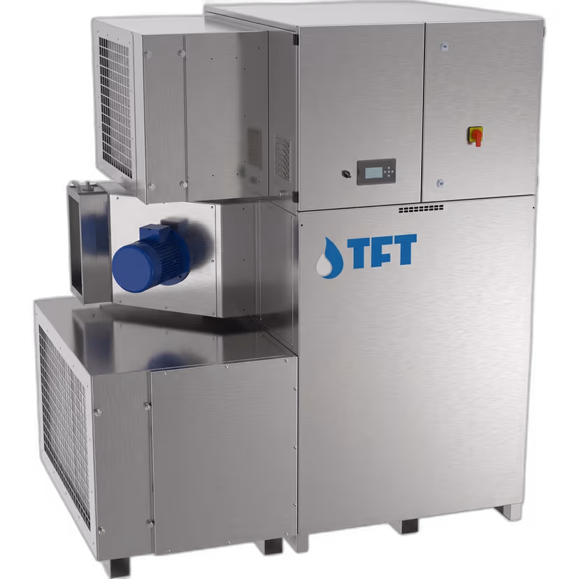
Silica-Gel Rotor: ADP Series (Main Tunnel)
- Application: Enrobed chocolate, praline, filled, low-temperature confectionery main tunnel
- Target DP: 0°C to -40°C
- Capacity: 2,000 – 9,500 m³/h air flow
- Strength: Low DP, sub-zero performance, rotor reliability
- Typical consumption: 0.6-1.0 kWh per L moisture (incl. regeneration)
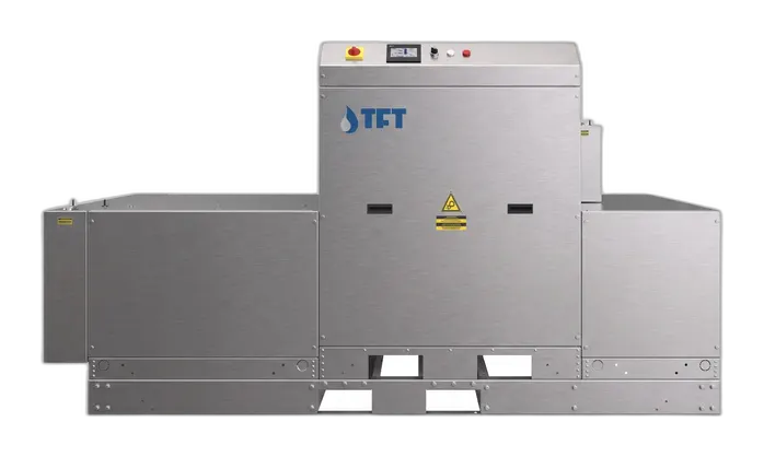
Hybrid Solution for High Ambient Moisture Loads
In coastal facilities where summer ambient air carries high absolute humidity, and in regions with wide seasonal moisture swings, a standalone silica-gel rotor system sees a marked rise in regeneration energy. For these cases a pre-cooling + silica-gel rotor hybrid is used: air is first cooled near the condensation limit by a DX or chilled-water coil, then the silica-gel rotor delivers the target dew point. The unit below integrates both technologies in a single cabinet, reducing total energy consumption by 25–35%.
System Design: Air Circulation, Buffer Zone, and Filtration
Correct equipment selection alone is not sufficient; the integration of the dehumidifier with the tunnel, air distribution, and operational discipline together determine final performance. Field data consistently show that "well-specified but poorly integrated" systems underperform "moderately specified but well integrated" systems.
Positive-Pressure Strategy
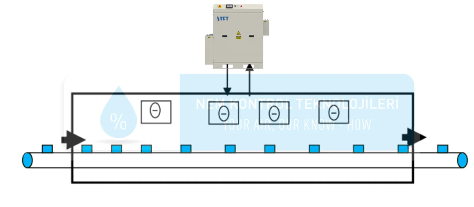
Maintaining the cooling tunnel at 5-20 Pa above ambient creates outward airflow at all openings, preventing infiltration. Dry air supplied by the dehumidifier is introduced at the tunnel head or mid-point; this air physically blocks ambient humid air from entering through openings or leakage points. Positive-pressure balance requires regular measurement; excessive positive pressure wastes energy and stresses doors and seals.
Buffer Zone (Inlet Vestibule) Design
Adding a buffer zone (inlet vestibule) between the cooling tunnel and the general production area makes the humidity transition two-stage. While the production area is typically 22°C and 50-60% RH, the tunnel interior is 12°C and 45% RH. The buffer zone bridges the two environments at 18°C and 45% RH, softening the transition shock. The buffer zone should have its own dehumidification system; a small-capacity silica-gel rotor unit (e.g. ADS 150-300) handles this duty. This approach reduces the main tunnel dehumidifier load by 20-40%.
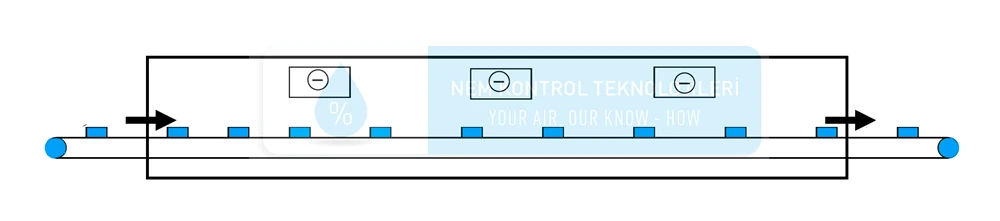
Air Distribution and Flow Pattern
Dry air supplied to the tunnel replaces the resident air through a dilution principle. For effective distribution, perforated ducts or plenum-based multi-point supply should be used rather than single-point injection. Air-change rate is recommended at a minimum of 10-15 ACH for chocolate tunnels, with 20-30 ACH for enrobed lines. Air flow should be counter-flow to product motion; the driest air should meet product nearest the tunnel inlet.
Door and Opening Management
Tunnel inlet/outlet openings are the largest infiltration source. To minimise these openings: PVC strip curtains (rapid-closing plastic strips) are fitted across the conveyor at the exact opening size; air curtains are combined with positive pressure; product entry height is kept minimal. Service doors should be interlocked, one open while the other is locked. This discipline prevents an estimated 50-100 litres/day of additional infiltration moisture.
Filtration: Food Hygiene and Equipment Protection
For food production filtration serves two purposes: first, preventing dust and particles from settling on the product; second, protecting the dehumidifier rotor/coil from contamination. Standard filtration follows the G4 pre-filter + F7 fine filter + F9 final filter chain. For high-hygiene lines, H13 HEPA filtration may be added. Filter replacement intervals must be monitored via differential pressure, with an automatic alert when the threshold is exceeded.
Case Study: Enrobed Chocolate Line (1,500 kg/hr)
The following is a summary of a field-applied enrobed chocolate cooling-tunnel project, using real engineering parameters. The customer is a chocolate factory in the Aegean region producing 4,000 tonnes per year. Their existing tunnel suffered a 12-15% sugar-bloom scrap rate during summer months, accompanied by rising customer complaints. The NKT engineering team carried out on-site psychrometric measurement and moisture-load analysis and produced a system recommendation.
Baseline Assessment
| Parameter | Existing Value | Target Value | Notes |
|---|---|---|---|
| Tunnel length | 32 m | 32 m (unchanged) | Linear, 3-zone |
| Conveyor width | 1.0 m | 1.0 m | Standard enrobed belt |
| Conveyor speed | 3.5 m/min | 3.5 m/min | 9-minute residence time |
| Tunnel internal temperature | 14°C → 8°C | 14°C → 8°C | 3-zone staged cooling |
| Tunnel internal RH (summer) | 72% RH | 45% RH | Critical improvement point |
| Tunnel internal dew point | +9°C | +2°C | Product surface 8°C, condensation unavoidable |
| Opening size (entry+exit) | 2 × 0.4 m² | 2 × 0.4 m² + PVC strip | PVC strip retrofit |
| Summer bloom scrap rate | 12-15% | < 1% | Target performance |
Moisture Load Calculation
For summer peak conditions (ambient 32°C, 75% RH; absolute humidity ~22 g/kg) the total tunnel moisture load:
- Infiltration (2 openings): 2 × 0.4 m² × 0.35 m/s × 1.2 kg/m³ × (22 − 4.5) g/kg × 3600 = ~21,200 g/h = 509 L/day
- Product carry-in moisture: 1,500 kg/h product, ~1% chocolate moisture imbalance = ~600 g/h = 14 L/day
- Personnel and operational door load: ~800 g/h = 19 L/day
- Total design load (20% safety factor included): ~27,000 g/h = 648 L/day
Proposed Solution
The NKT engineering team's recommendation followed a three-layer system architecture:
- Main process dry-air supply: ADP series silica-gel rotor dehumidifier (5,000 m³/h air flow, 0°C dew point guaranteed). Supplied at the tunnel head via a perforated duct.
- Buffer zone humidity control: Small-capacity silica-gel rotor unit (ADS 150-300, ~250 L/day equivalent capacity). Maintains the inlet vestibule at 18°C and 45% RH.
- Positive pressure and air curtain: 200 mm-depth PVC strip curtain at tunnel entrance; an 8 m/s air curtain behind it. Tunnel interior held at 12 Pa positive pressure.
Results (3-month follow-up measurement)
| KPI | Before | After | Improvement |
|---|---|---|---|
| Tunnel inlet dew point (summer) | +9°C | +1.5°C | −7.5°C |
| Tunnel internal RH (summer) | 72% | 44% | −28 points |
| Sugar-bloom scrap rate | 13.5% (summer peak) | 0.6% | −12.9 points |
| Customer-return rate | 2.8% | 0.3% | −2.5 points |
| Monthly recovered production value | — | ~38 tonnes | Capacity recovered |
| System payback period | — | ~14 months | Investment amortisation |

Energy Efficiency and Periodic Maintenance
The cooling tunnel + dehumidifier combination is among the highest-consuming systems in a modern food production facility. It can account for 20-35% of total plant energy consumption. Sound design decisions and disciplined operations can reduce this share significantly.
Energy-Optimisation Strategies
- VFD for fan and compressor control: Variable-frequency control matched to production rate yields 25-40% energy savings at partial load (fan power scales with the cube of airflow).
- Synchronisation: The dehumidifier should turn off when the tunnel stops; it should also be activated 15-30 minutes before tunnel start to bring the environment to target.
- Waste-heat recovery: Heat rejected from the cooling-tunnel condenser can pre-heat the silica-gel regeneration air, yielding 15-25% additional savings.
- Night/weekend mode: Outside production hours, target dew point can be relaxed (up to 55% RH) and airflow reduced, saving 50-70% energy.
- Buffer-zone approach: The main tunnel's moisture load drops 20-40% with a buffer zone.
- Smart control: Setpoint optimisation tied to seasonal ambient data delivers an average annual 12-18% savings.
Periodic Maintenance Schedule
| Frequency | Action | Purpose |
|---|---|---|
| Daily | Drain line check, dew-point measurement, pressure-difference monitoring | Early detection of blockage and drift |
| Weekly | Tunnel interior cleaning, drain siphon flush, door/curtain mechanical inspection | Hygiene, seal integrity |
| Monthly | Pre-filter replacement (G4/F7), evaporator coil cleaning | Airflow preservation, heat-transfer efficiency |
| Quarterly | Fine-filter replacement (F9), rotor seal inspection, sensor calibration | Dew-point accuracy, performance preservation |
| Half-yearly | Compressor function test, regeneration heater cleaning, comprehensive system analysis | Mechanical health, energy efficiency |
| Annual | Full CIP cleaning, ductwork biofilm testing, rotor performance test, leakage test | Food hygiene certification, long service life |
Maintenance Discipline and Performance Preservation
Neglecting a disciplined maintenance programme typically causes 5-10% annual performance degradation; after three years a system runs at only 70% of its initial performance. Disciplined maintenance, in contrast, allows the system to retain near-day-one performance for 10+ years. This represents a critical difference for investment amortisation.
NKT Technical Solutions and the TFT Partnership
NKT, Nem Kontrol Teknolojileri brings decades of field experience in industrial humidity control to the design and delivery of cooling-tunnel dehumidification systems for the chocolate, confectionery and food sectors in Türkiye. Our engineering team evaluates each facility on its own psychrometric parameters and offers project-specific system recommendations rather than off-the-shelf product lists. This approach prevents producers from buying unnecessarily large equipment and optimises the energy budget around the real moisture load on the line.
Strategic Partnership: TFT
NKT sustains a strategic manufacturing and supply partnership with TFT, Tecnofrigo Tuscany Srl (Italian industrial dehumidifier manufacturer), a leader in the global desiccant and dehumidification technologies market. This partnership gives Turkish producers access to European-standard AISI 304 stainless-steel silica-gel rotor systems (TFT ADP / ADE / AD series) with local engineering support and rapid spare-parts availability. TFT brings more than 30 years of desiccant-rotor manufacturing experience; its rotor sealing design and low dew-point performance are reference standards for the industry.
Scope of Service
- Site analysis: Psychrometric measurement at the existing tunnel, infiltration-load calculation, bloom root-cause analysis
- Engineering design: Integrated system recommendation covering tunnel + dehumidifier + buffer zone; CAD drawings and airflow simulations
- Correct product selection: Project-specific optimum selection across silica-gel rotor ADP, AD and ADS ranges based on capacity and target dew point
- Commissioning: On-site installation supervision, initial performance verification, operator training
- Periodic service: Maintenance contracts, remote monitoring, performance audit
- Energy-optimisation consulting: Seasonal setpoint adjustment, waste-heat recovery recommendations