Definition
A safety sensor located in the HVAC supply duct that prevents supply-air relative humidity from exceeding a danger threshold (typically 90–95% RH); guards against condensation, condensate accumulation and duct-hygiene issues.
Detailed Explanation
A high-limit sensor (HHL or HL) is the secondary safety layer in humidification control. While the primary control sensor (room or return duct) chases the target RH, transient overdose events (e.g. a door opening drops RH sharply → device overshoot) can push supply RH above 95%. At that point supply-air condensation risk begins (duct walls, sensors, downstream coils). The high-limit sensor typically slows the humidifier above 85% RH and shuts it down above 90% RH. It works via PLC override: the main PID is cut, the system enters safe mode.
Why It Matters
A high-limit sensor prevents four main problems: (1) IN-DUCT CONDENSATION — at 95%+ RH supply air hitting cold duct walls condenses; duct-hygiene breach, corrosion, downstream coil wetting. (2) DOWNSTREAM EQUIPMENT DAMAGE — a wet cooling coil loses pressure and efficiency; a wet HEPA can burst, breaching hygiene class. (3) SPACE HYGIENE BREACH — cleanrooms, hospitals and pharma face microbial growth + contamination risk at excessive RH. (4) CONTROL-LOOP STABILITY — overshoot lengthens PID correction; early high-limit action keeps the RH band tight.
Practical Example
A printing plant in Konya had no high-limit sensor in the original design. On cold winter mornings, when heating + humidifying ran together, supply air reached 94–96% RH for 2–3 minutes; the duct saw 50–80 ml/h of condensate drip and the downstream filter wetted. NKT retrofit: a humidity high-limit sensor was placed in the supply duct 3 m after the manifold (slow at 88%, stop at 92%). Over the next 12 months: zero drip, filter life doubled.
Engineering Note
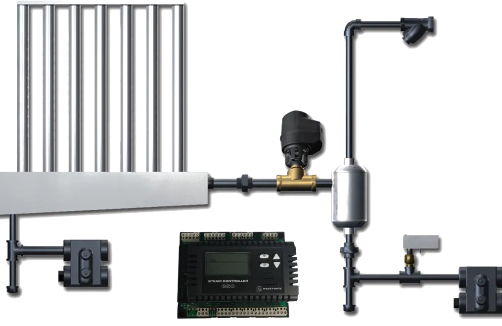
High-limit sensor placement rules: (1) In the supply duct, at least one absorption distance + 1 m after the manifold; (2) In a developed-flow region (at least 5× duct diameter before any elbow or damper); (3) Sensor tip at duct centre, not on the top or side wall. Control logic: typical 3-band — 85% (slow, drop capacity to 50%) → 90% (stop) → 95% (alarm + BMS notify + event log). The high-limit sensor must be independent and a different brand from the primary (single-point-of-failure protection).
NKT Application Link
For tight-RH facilities (hospital, pharma, museum, sensitive printing) NKT recommends a high-limit sensor as standard; the commissioning protocol includes position verification, threshold tuning and alarm testing as mandatory steps. The NKT - Climate Track platform trends high-limit trigger count + duration; frequent triggers are an early warning that PID re-tuning is needed.