Definition
Positioning humidity (RH) and temperature (Tdb) sensors at the correct location in a duct or space so they read representative values; it directly affects control stability and energy efficiency.
Detailed Explanation
Humidity sensor placement is the act of positioning the sensor where its RH/Tdb reading represents the real process condition. Three typical placements: (1) Duct sensor — mounted in the AHU supply or return, reads bulk flow conditions; (2) Room sensor — wall- or height-mounted, reads average room conditions; (3) Process-point sensor — close to a specific piece of process equipment (printing roll, product conveyor, museum vitrine).
Each placement implies a different control strategy: a duct sensor targets AHU global performance, a room sensor targets occupant comfort, a process sensor targets product quality. Wrong placement → wrong control → either wasted energy or lost quality.
Why It Matters
Bad sensor placement causes five typical problems: (1) Sensor too close to a steam manifold (inside the absorption distance) → wet droplets on the sensor, RH reads 95–100% continuously, the control loop assumes "enough moisture" while the room is still dry. (2) Sensor near a heat source (radiator, window, equipment) → reads high Tdb and low RH, the loop overhumidifies → wasted energy. (3) Near a door/window → outdoor leakage perturbs the sensor, control oscillates. (4) Single-point measurement in a large space → local condition is far from the average; at least 3–4 points are recommended. (5) Sensor in high-velocity flow (> 5 m/s) → turbulence error.
Correct placement: beyond the absorption distance, away from heat sources, in a region of laminar flow, at the centre of the room or at the process-critical point. For sensitive processes (pharma, museum, printing), two redundant sensors plus a median filter are recommended.
Practical Example
A spinning mill in Bursa complained of constant RH oscillation; the sensor sat in the AHU return duct at 0.8 m, but the return duct ran near a door. Site investigation showed the sensor swung 5–8% RH every time the door opened. Solution: the sensor was relocated 4 m further along into a straight duct section, and a second room-centre sensor was added (median control). RH oscillation dropped from ±6% to ±1%. Modulation time fell 22%, with ≈ 14% annual electricity savings.
Engineering Note
Sensor placement standards: ASHRAE 41.6 (laboratory humidity measurement), EN 16798-3 (ventilation system performance), ISO 7726 (thermal environment). Industry practice: a duct sensor is placed at least 5× the duct diameter past a manifold, or at least 2 m; a room sensor is at 1.5–1.8 m height, 30 cm from any wall, and on an interior wall (not an exterior one); a process sensor is in the critical airstream and at least 1 m from any active heat source.
For sensitive applications (±1–2% RH band), two standard technologies: (a) capacitive RH sensors (industrial-class RH/T sensor, room-type RH/T sensor) — fast response (10–30 s), ±2% RH accuracy, 5–7 years drift resistance; (b) optical chilled-mirror dew-point meters (reference-grade, ±0.1°C dp) — used as calibration references. Calibration check every 6 months; full calibration every 12–24 months.
NKT Application Link
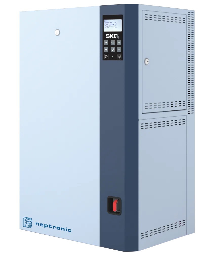
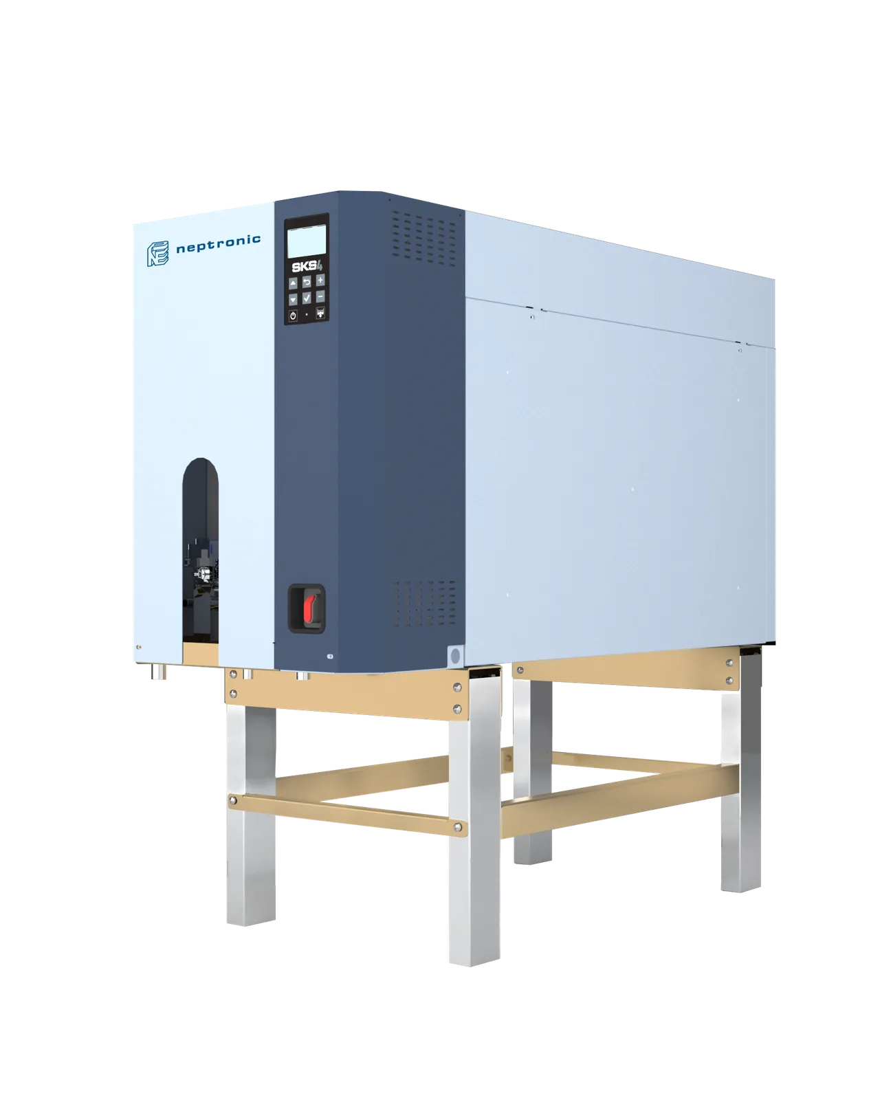
For this application NKT – Nem Kontrol Teknolojileri supplies the Neptronic SKE4 resistive steam humidifier and the Neptronic SKS4 steam-to-steam humidifier. It supports unit selection with capacity calculation and technology matching based on space conditions, target temperature and RH (or dew point) and moisture load, and provides technical service and spare parts. Design, installation and commissioning remain within the scope of the facility's designer and contractor.
Related Academy Articles
Related Products
NKT products related to this term