The real performance of a steam humidification system depends as much on how its steam enters the airstream as on how much steam is produced. The steam distribution manifold and absorption distance are two engineering parameters that often get attention only after device selection, but in the field they decide the success or failure of the system. A poorly placed manifold can leave a correctly sized unit operating at only 50–70% of its nominal capacity, drip condensate in the duct, and on layouts with the wrong duct velocity it lets water collect inside the HVAC channel. This guide explains what a steam distribution manifold is, what governs the absorption distance, and the design rules that keep both right.
What Is the Steam Distribution Manifold?
A steam distribution manifold is a stainless-steel pipe (single or multi-port) that splits the dense steam jet leaving the humidifier into a homogeneous distribution across the HVAC duct or room cross-section. Structurally simple (one or more perforated/nozzled pipes) its engineering value is determined by diameter, hole geometry, position and length.
A typical distribution manifold has the following components:
- Main pipe body: Stainless steel (AISI 304/316), 32–80 mm diameter, sized for steam flow.
- Steam outlet holes / nozzles: A row of holes or directional nozzles on the top face, distributing along the pipe length.
- Steam inlet: Insulated flexible hose connection from the unit, typically 25–60 mm internal diameter.
- Condensate drain: At the bottom end, a sloped line that either returns to the unit or discharges to a separate drain.
- Insulation: External wall insulation; reduces ambient heat loss and outer-surface condensation risk.
The NKT catalogue carries two main types: the Neptronic SKD direct-steam-injection manifold (device + manifold in one module) and the Neptronic Multi-Steam distribution system (multiple parallel pipes for large-section ducts). Both are manufactured to project-specific calculated geometry.
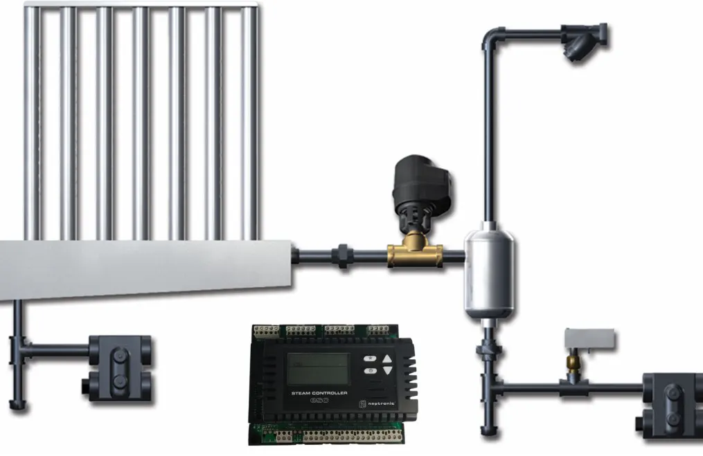
Figure 1: Steam Distribution Manifold and Absorption Distance Inside the Duct
Why Steam Distribution Is Critical
A steam humidification system has three components: the device (steam generator), the distribution (manifold + piping) and the airflow (HVAC duct or room). About two-thirds of field problems come not from the device itself but from the distribution-airflow matching. A correctly sized device with poor distribution still produces:
- Nominal capacity loss: When steam does not distribute homogeneously across the duct, part of it condenses on the wall, actual humidification capacity stays at 50–75% of the nameplate value.
- Condensate dripping: Condensed steam pools at the duct floor; it drips into served rooms, creating microbiological risk and surface staining.
- Sensor misreading: RH measured before absorption is complete reads 5–15 points higher than reality; the PID takes wrong actions, the setpoint drifts.
- Duct corrosion: Continuous condensation on galvanized/carbon-steel duct walls accelerates corrosion; typical duct life drops from 15 years to 5–7.
- Microbiological risk: Pooled condensate is a favourable environment for Legionella, Pseudomonas and other colonization, especially critical in hospitals and pharma.
Distribution design therefore cannot be considered separately from device selection. In the NKT proposal process, device + distribution is always treated as one design unit.
What Is Absorption Distance?
Absorption distance (L_abs) is the downstream distance over which steam leaving the distribution manifold fully mixes with the airflow and transitions into the invisible gas phase. Measured from the steam outlet, expressed in meters. Along this distance, steam particles mix with air, temperature equilibrates and the visible steam plume disappears.
Typical values:
| Design Profile | Typical L_abs | Context |
|---|---|---|
| Ideal: high velocity + low starting RH | 0.5 – 1.0 m | 3 m/s air, 30% RH inlet, 25°C. |
| Typical HVAC duct | 1.0 – 2.0 m | 2 m/s air, 40% RH inlet, 22°C. |
| Long: low velocity + high RH | 2.0 – 4.0 m | 1 m/s air, 55% RH inlet, 18°C. |
| Critical: very low velocity + near-saturation | > 4 m | < 0.5 m/s air, 65%+ RH; design review required. |
In practice L_abs is calculated by the device manufacturer (Neptronic and others) from duct velocity, temperature, inlet RH and steam load. In every NKT proposal, a site-specific L_abs calculation drives the manifold position and length design.
Factors Affecting Absorption Distance
L_abs is set not by a single formula but by the interaction of five independent parameters. Each affects in a different direction and with a different magnitude:
1. Duct Air Velocity
The single most influential parameter. As duct velocity rises, turbulence rises, steam mixes faster, L_abs shortens. Typical range: 1.5–4 m/s. Below 1 m/s, L_abs lengthens dramatically; above 5 m/s, noise and pressure-loss problems emerge. Optimum band 2–3 m/s. At the manifold position, this velocity should be confirmed by an on-site duct-velocity measurement.
2. Air Temperature
As temperature rises, the air's water-holding capacity rises exponentially; steam absorbs faster. A 20°C → 25°C shift shortens L_abs by 15–20%. At low temperatures (cold-air mixing duct, fresh-air inlet), L_abs lengthens; for this reason the manifold is placed AFTER the fresh-air heating coil.
3. Inlet Relative Humidity
The closer the air is to saturation, the slower the absorption. 30% RH inlet → short L_abs; 60% RH inlet → long L_abs. Above 75% RH any extra steam injection enters condensation risk; for this profile, in-duct humidification should be replaced with in-room atomisation.
4. Steam Load (Device Capacity)
Higher load → denser steam plume → longer mixing time. Distributing the same load over multiple parallel manifolds instead of injecting from a single point shortens L_abs significantly. The Neptronic Multi-Steam distribution system applies this principle in high-capacity systems.
5. Steam Temperature / Superheat
If steam at the manifold is around 100°C, absorption is fast; if heat loss has dropped its temperature, condensation starts inside the manifold and droplets carry over. So the device-to-manifold steam hose must be insulated and kept short (typically < 4 m).
L_abs ≈ k × (m_steam / v_air) × f(T, RH)Where k = pipe-geometry constant, m_steam = steam load (kg/h), v_air = duct velocity (m/s), f(T, RH) = temperature-RH correction factor.
Why Condensation Occurs
In-duct condensation happens when steam contacts a surface whose temperature is below the dew point. Four main causes:
1. Cold-Surface Contact
Steam contacting duct wall, elbow, filter frame or cooling coil at a surface temperature below the dew point condenses immediately. A galvanized duct can sit at 12–15°C in winter; outlet steam is loaded with humidity and converts to droplets quickly.
2. Obstacle Inside Absorption Distance
If an elbow, filter or coil sits inside L_abs, steam impinges on the surface as droplets and condenses. Design must always keep these obstacles OUTSIDE L_abs + 0.5 m safety margin.
3. Over-Dosing / Setpoint Overshoot
If device calibration is off or the control algorithm is poor, excess steam is injected above the target RH. The saturated air condenses spontaneously inside the duct; this is a PID-tuning or sensor-position issue.
4. Steam Hose Cooling
If the flexible hose between unit and manifold is uninsulated or too long, steam cools and condensate collects at the hose end. These droplets carry into the manifold and drip directly into the duct.
Post-Fan Placement
The most fundamental rule of manifold placement: place it AFTER the fan, heating coil and filter, BEFORE the cooling coil and the sensor. This sequence is mandatory for four reasons:
- Post-fan turbulence: Air leaving the fan is turbulent; this accelerates steam mixing and shortens L_abs. Pre-fan placement sits in laminar flow and slows mixing.
- After heating coil: Warm air has high steam-holding capacity; mixing is fast, condensation risk is low. Injecting steam into cold air is an open invitation to condensation.
- After filter: Filter surfaces trap steam droplets and become a microbiological substrate; all filters are placed upstream of the manifold.
- Before cooling coil: Cooling coils condense steam droplets; steam reaching the coil before absorption is complete drips on the coil.
Typical HVAC train ordering: fresh-air mixing → pre-heat coil → filter → fan → steam manifold (+ L_abs distance) → sensor → main heating/cooling coil → distribution duct.
Distance to Elbows/Filters/Coils
The critical rule for manifold placement: no obstacle inside the absorption distance. The table below lists typical obstacle types and the recommended minimum distance from the manifold outlet:
| Obstacle Type | Minimum Distance | Reason |
|---|---|---|
| 90° elbow | L_abs + 1.0 m | Centrifugal force + condensation on the outer wall. |
| 45° elbow | L_abs + 0.5 m | Lighter centrifugal effect, still risky. |
| Reducer / expander | L_abs + 0.5 m | Velocity change upsets turbulence balance. |
| Cooling coil | L_abs + 1.5 m | Cold surface produces direct condensation. |
| HEPA filter | L_abs + 2.0 m | Filter accumulates droplets + mineral aerosol; clogs. |
| Damper | L_abs + 0.5 m | Condensation on the damper blade surface. |
| Humidity sensor | L_abs + 0.5 m | Accurate RH reading requires full mixing. |
| Temperature sensor | L_abs + 0.3 m | Local steam accumulation distorts temperature reading. |
Drain Slope and Condensate Management
Even in perfectly designed systems, a small amount of condensate forms at the bottom of the distribution manifold, this is a physical inevitability. How this condensate is managed is the measure of design quality.
Slope Rule
The distribution manifold should not be installed horizontally. It is mounted with at least 1% (preferably 2%) slope toward the device side; condensate flows back by gravity. A T-connection + condensate trap at the pipe end provides the drain line; this line is also sloped (2%+) to the drainage point.
Condensate Trap (Siphon)
The trap prevents duct air pressure from pushing condensate back into the manifold via the drain line. U-trap is common; minimum 10–15 cm depth is required. If the trap is not placed correctly, duct air pressure forces condensate back and pools in the manifold.
Hose Insulation
The flexible hose between device outlet and manifold must always be insulated. Typical insulation thickness 15–25 mm; insulation class is high-temperature resistant (rock wool or high-temperature EPDM). Without insulation, steam loses 10–15°C over 4 m and condenses at the hose end.
Steam Lance
For very short distribution in small ducts, the steam lance is the single-pipe solution. Simpler but limited capacity; suitable for 20–60 kg/h steam typically.
Manifold Selection
The correct distribution manifold is chosen across three parameters: steam load (device capacity), duct cross-section (width × height) and application profile (hygienic, sensitive, comfort). The NKT catalogue carries two main products:
Neptronic SKD: Direct Steam Injection
The SKD family combines device + distribution manifold in a single compact module. Designed for connection to an existing facility steam boiler; routes steam directly into the duct. Typical capacity 5–600 kg/h; ideal for small-to-mid-scale HVAC systems. The unit mounts to wall/rack, the manifold inserts into the duct.
Neptronic Multi-Steam: Multi-Parallel Manifold
Multi-Steam is a distribution system of multiple parallel pipes for large HVAC duct cross-sections (over 1 m × 1 m) and high-load systems. It injects steam not from a single point but from multiple manifolds spread across the duct cross-section; this halves L_abs. Typical capacity 100–2,000 kg/h.

SKE4 as Steam Source
When a resistive steam humidifier (Neptronic SKE4) is chosen as the steam source, distribution is achieved with a manifold + flexible hose from the device outlet. The SKE4 + manifold combination is the standard configuration for projects without facility steam. With RO/DI water, it is ideal for hygienic facilities.
Most Common Mistakes
The most common field mistakes in distribution design from the NKT project portfolio, alongside their correct counterparts:
WRONG
0.5 m between manifold and sensor; sensor reads near saturation, the PID throttles back, capacity drops 40%.
RIGHT
Manifold → L_abs (1.5 m) + 0.5 m safety = sensor 2.0 m away; true RH reading after full mixing.
WRONG
90° elbow 1 m downstream of the manifold; continuous condensation on the elbow's outer wall, water dripping into the room.
RIGHT
Distance between manifold and elbow L_abs + 1 m = 2.5–3 m; full absorption before the elbow, no dripping.
WRONG
6 m uninsulated hose between unit and manifold; 200 mL/h condensate at the hose end, dripping at the manifold.
RIGHT
Hose < 4 m, 20 mm insulation, 2% slope toward the unit; condensate trap returns it, no dripping at the manifold.
WRONG
Single manifold mounted vertically in a 1,200-mm-tall duct; steam stacking at the bottom, dryness at the top.
RIGHT
Multi-Steam multi-parallel manifold or two separate manifolds; homogeneous distribution across the section, ±3% RH band.
WRONG
Manifold 0.8 m upstream of the cooling coil; continuous condensation on the coil surface, drain overflow, hygiene breach.
RIGHT
Distance between manifold and cooling coil L_abs + 1.5 m = at least 3.5 m; coil contact only after full absorption.
NKT Approach
NKT, Humidity Control Technologies delivers steam distribution design as one engineering package together with equipment selection. As Neptronic's official Turkish distributor, the device + manifold + commissioning chain is delivered end to end. Standard package steps:
- Site duct measurement: Existing HVAC train cross-section, duct velocity, temperature and inlet RH profile recorded.
- L_abs calculation: Absorption distance calculated from device capacity + duct velocity + temperature + RH inputs; safety margin added.
- Manifold position design: Fan/coil/sensor distance rules applied to draw the optimum manifold position.
- Drainage + insulation plan: Slope, condensate trap, hose insulation thickness and steam-pipe diameter defined.
- Product matching: SKD (direct injection), Multi-Steam (multi-parallel) or SKE4 + manifold (steam source) selection.
- Commissioning + sensor calibration: First-week trend log analysis, manifold position/orientation adjustment if needed, PID fine-tuning.
This approach removes the "device arrived, manifold arrived separately, installer placed it on site" composition; every project is delivered as a site-specific design output.
Steam distribution manifold and absorption distance are two engineering parameters that decide the field performance of a steam humidification system. The conversion of nameplate capacity into actual capacity depends on correct manifold placement and ensuring the absorption distance completes without encountering an obstacle. Bad design produces 30–50% loss of nominal capacity, condensate dripping, hygiene risk and long-term duct corrosion.
Correct design is the intersection of four rules: (1) the manifold sits AFTER fan + heating coil + filter, BEFORE the cooling coil and the sensor; (2) L_abs is calculated and no obstacle sits inside L_abs + safety margin downstream of the manifold; (3) drain slope, condensate trap and hose insulation are applied to standard; (4) for large duct cross-sections, multi-parallel systems (Multi-Steam) are used instead of a single manifold.
As Neptronic's official Turkish distributor, the NKT engineering team delivers site-specific design for each project with SKD direct-steam-injection manifolds, Multi-Steam multi-distribution systems and SKE4 + manifold combinations. With this approach, device selection and distribution design are delivered not as separate decisions but as one engineering whole.