Definition
The downstream distance over which injected steam fully mixes with the air and no visible droplets remain; typically 0.3–3 m, longer at high RH and low supply velocity.
Detailed Explanation
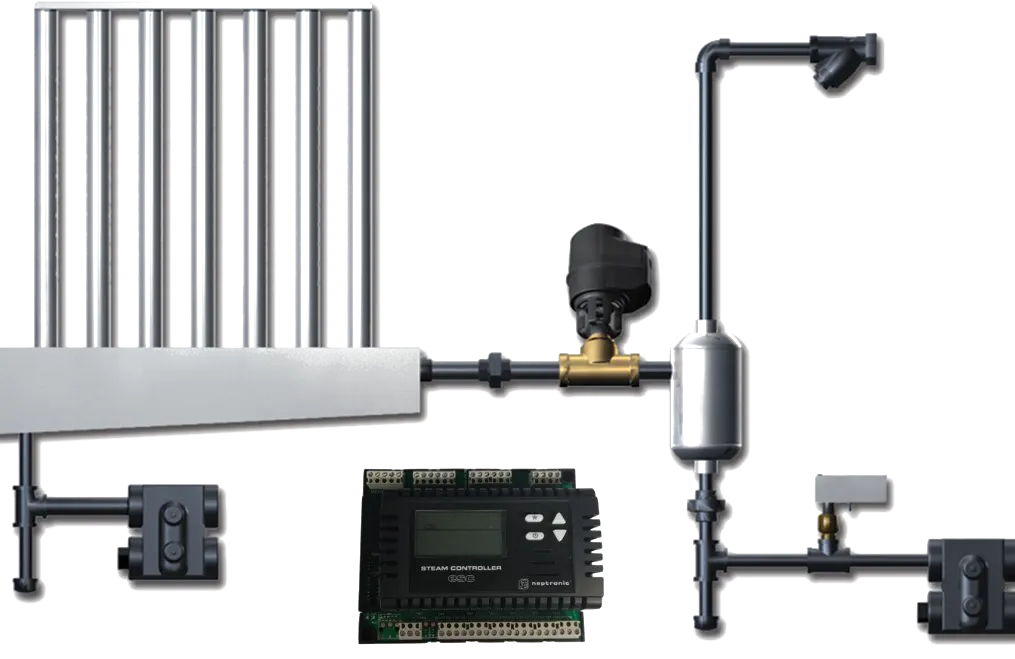
Absorption distance (BL) is the downstream length over which steam leaving the manifold jets fully evaporates into the airstream so that no visible droplets/mist remain. Inside this distance, condensate can form on the duct surface or on downstream equipment (filters, coils, sensors).
It depends on: (1) steam mass flow — more steam, longer distance; (2) air temperature — low Tdb makes steam condense faster, lengthening the distance; (3) RH — inlet RH > 50% lengthens the distance; (4) air velocity — under 1.5 m/s lengthens the distance; (5) duct cross-section and manifold geometry — narrow duct plus long manifold shortens it. Typical range 0.3–3 m; in extreme cases (high RH > 70%) 5+ m is possible.
Why It Matters
An insufficient absorption distance causes three main issues: (1) condensate on duct walls → corrosion, mould, hygiene risk; (2) condensate on downstream sensors/filters/coils → wrong sensor readings, unstable control, blocked filters, derated coils; (3) drips onto equipment under the duct → damage to sensitive electronics or food equipment.
For that reason, the downstream "free duct" length is verified at manifold-selection time; the sensor must always sit beyond the absorption distance. When the available downstream length is short (an elbow, coil, or distribution box follows), two remedies are used: (a) a jacketed (insulated) manifold with a shorter absorption distance; (b) increasing air velocity by narrowing the duct cross-section — fan pressure rises but distance shortens. NKT verifies the distance per facility using OEM tools (Neptronic Distance, humidification sizing tool).
Practical Example
A bakery cold-storage corridor in Eskişehir: AHU outlet 22°C, supply RH 45% (high inlet), target RH 75%, air velocity 1.2 m/s, flow 8,000 m³/h. The first design used a standard Neptronic SKD-CK manifold; the absorption-distance calculation returned 4.5 m — but only 2 m of free duct existed past the manifold (an elbow followed). Solution: a jacketed Neptronic SKD-AC manifold plus a duct restriction that lifted air velocity to 2 m/s; the new absorption distance is 1.7 m. The system runs condensate-free.
Engineering Note
OEM tools approximate absorption distance as: BL = K × (m_steam / V_air) × f(RH, Tdb, manifold type); the K coefficient is set by OEM laboratory data. On-site validation during commissioning: a thermal camera (looking for cool spots) or a moveable downstream RH sensor at every 0.5 m. Condensate appears as 5–8°C cooler spots in the thermal image.
Alternative — ULTRASONIC ATOMISATION: where very high RH is required (> 75%) and the absorption distance does not fit a steam system, adiabatic atomisation is recommended; droplet diameter is very small (5–15 μm), evaporation is rapid, and the absorption distance shrinks to 0.5–1 m. Hygiene and control stability, however, are below those of a steam system.
NKT Application Link
In NKT projects the absorption-distance calculation is a mandatory field of the manifold-selection form; design uses the Neptronic Distance Calculator together with AHU geometry (duct width, velocity, downstream equipment layout). The commissioning checklist includes "downstream 2 m condensate check" — the post-manifold zone is scanned with a thermal camera. The NKT - Climate Track platform continuously trends the downstream RH sensor; an abnormal drop or rise is a manifold/absorption signal.