The real performance of a steam humidification system depends as much on how its steam enters the airstream as on how much steam is produced. The steam distribution manifold and the absorption distance are two engineering topics that often get attention only after equipment selection, yet in the field they decide whether the system works. A poorly selected or poorly placed distributor can stop even a correctly sized unit from holding the target humidity, cause condensate dripping and let water collect inside the duct. This guide explains what a steam distribution manifold and the absorption distance are, which conditions set the distance, and the basic rules for correct placement.
What Is the Steam Distribution Manifold?
A steam distribution manifold (steam distributor) is a stainless-steel pipe that spreads the dense steam flow coming from a steam humidifier evenly across the section of an HVAC duct or air handling unit. Structurally it looks simple: one or more nozzled pipes. Its engineering value lies in the number and spacing of the tubes, the nozzle layout, its position and its length.
A typical distribution manifold has the following components:
- Pipe body: 304 stainless steel, built to a custom length for the duct; the pipe diameter is set by the manufacturer according to the unit's steam outlet.
- Nozzles: Nozzles along the pipe draw steam from the centre of the tube and release it into the airstream, so condensate formed on the tube wall cannot escape into the duct. On models such as the S.A.M.E2 the nozzles are arranged in two rows at 90°.
- Steam inlet: Connection for the steam hose or insulated rigid pipe coming from the unit.
- Condensate outlet: The pipe is mounted with a slope, and condensate formed inside is returned to the unit or to a steam trap.
- Insulation: On double-wall insulated distributors such as Multi-Steam™ HD, heat released into the air and condensate formed in the tube are reduced.
For in-duct distribution, the Neptronic range includes the S.A.M. (Short Absorption Manifold) and dual-row S.A.M.E2 distribution wands, and the Multi-Steam™ SD/HD/HDR systems built from many vertical tubes spread across the section. All are custom-built to the duct or air handler dimensions.
Figure 1: Steam Distribution Manifold and Absorption Distance Inside the Duct
Why Is Steam Distribution Critical?
A steam humidification system has three components: the unit that generates steam, the distributor that delivers it into the duct (manifold plus steam line), and the airflow that carries it. Many field problems stem not from the unit itself but from how distribution is matched to the airflow. Even a correctly sized unit suffers the following with poor distribution:
- Capacity loss: When steam is not spread evenly across the section, or hits an obstruction, part of it condenses on surfaces; some of the steam produced never reaches the space and the target humidity is missed.
- Condensate dripping: Condensed steam collects on the duct floor, leaks through seams or is carried as droplets into the served rooms.
- Sensor error: A sensor that measures before the steam has fully mixed reads higher than the true duct average; the control cuts the steam too early and the space stays below target.
- Duct corrosion: Continuous condensation accelerates corrosion of galvanized or carbon-steel duct and shortens its life.
- Microbiological risk: Standing water in the duct is a favourable medium for Legionella and other bacteria; in hospitals and pharmaceutical plants this risk is not acceptable.
Distribution design therefore cannot be separated from equipment selection; the unit and the distributor should be selected together from the same duct data.
What Is Absorption Distance?
Absorption distance is the distance over which steam leaving the distributor fully mixes into the airstream and the visible mist disappears; it is measured in metres from the distributor in the direction of airflow. Steam leaves the distributor as an invisible gas. On meeting cooler air, part of it condenses into micron-sized droplets, and the white plume we see is made of these droplets. Further downstream the droplets re-evaporate; the point where the plume ends marks the end of the absorption distance.
Manufacturers also quote a non-wetting distance: the distance beyond which surfaces downstream of the distributor no longer get wet. It is usually shorter than the full mixing distance. The two should not be confused in design: obstacles must sit at least beyond the non-wetting distance, while humidity sensors belong at the point where mixing is complete.
Absorption distance is not a fixed value. It is determined with the manufacturer's selection software or charts, using inlet RH, RH after humidification, air velocity, air temperature and the number and spacing of dispersion tubes. Neptronic data give an absorption distance under 1.5 m for the S.A.M. and S.A.M.E2 distributors and under 1 m for Multi-Steam™ systems. The actual value for a project is calculated for that duct's conditions.
Factors Affecting Absorption Distance
Absorption distance is set not by a single formula but by several interacting conditions. That is why manufacturers give it through selection tables and software based on test data rather than a simple equation.
1. RH After Humidification
The most decisive condition is how close the air gets to saturation after humidification. The closer it gets, the slower the droplets re-evaporate and the longer the plume. Take a 1.0 × 0.6 m duct receiving 20 kg/h of steam, with air arriving at 22 °C and 40% RH: at 4 m/s the RH after humidification stays around 52%, while at 1 m/s the same steam goes into less air and the RH rises to 86%. Duct humidity is therefore capped with a high-limit humidity sensor downstream of the distributor.
2. Duct Air Velocity
Air velocity works in two directions. For the same humidification duty, faster air carries the steam further while it mixes, so the distance grows. At low velocity, as the example above shows, the same steam goes into less air, pushing it towards saturation, which also lengthens the distance. Velocity is therefore assessed together with the RH after humidification. The common design range at the distributor position is 2.5–4 m/s, and the velocity should be verified on site with a duct-velocity measurement.
3. Air Temperature
The amount of moisture air can hold rises exponentially with temperature: saturated air carries about 14.7 g/kg of water vapour at 20 °C and about 20.0 g/kg at 25 °C. Steam injected into cold air approaches saturation sooner, and the distance grows. For this reason steam is injected after the heating coil, where the air is warm.
4. Steam Load and Distributor Geometry
A large steam flow from a single tube forms a big, long plume. When the same steam is split across several tubes or many nozzles spread over the section, each plume is smaller and the distance shortens. The dual-row S.A.M.E2 and the multi-tube Multi-Steam™ distributors work on this principle.
5. Condensate in the Steam Line
In an atmospheric-pressure humidifier, steam is saturated at about 100 °C. When saturated steam loses heat it does not cool down; an amount of steam equal to the heat lost condenses. Condensate formed in an uninsulated or long hose drips into the duct if it reaches the distributor. The steam line is therefore kept short, insulated and sloped; per the Neptronic installation manual, the total flexible hose length should not exceed 5 m.
Why Does In-Duct Condensation Occur?
In-duct condensation occurs when a surface in contact with steam or humid air is below the air's dew point, or when droplets that have not yet evaporated strike a surface. Four main causes:
1. Cold-Surface Contact
If surfaces such as the duct wall, an elbow, a filter frame or a cooling coil are below the dew point, moisture condenses on them. For example, air at 22 °C has a dew point of about 11 °C at 50% RH and about 14 °C at 60% RH; in winter the inner surface of a duct passing through a cold area can fall below these values.
2. Obstacle Inside the Absorption Distance
If an elbow, damper, filter or coil sits inside the absorption distance, droplets that have not yet evaporated strike it and collect as water. Obstacles are therefore always kept outside this distance.
3. Over-Humidification
If the control sensor is in the wrong place or duct humidity is not capped, the air in the duct approaches saturation and condensation becomes unavoidable. A high-limit humidity sensor downstream of the distributor reduces or stops the steam in that case.
4. Condensate in the Steam Line
If the hose between the unit and the distributor is uninsulated, too long, sagging or insufficiently sloped, steam condenses in proportion to the heat lost and condensate collects at the low points. If this water reaches the distributor it drips straight into the duct.
Position in the Air Handler
The basic placement rule is that the steam distributor goes after the heating and cooling coils, in the section where the air is warmest and the velocity profile is even. There are four reasons:
- Warm air holds more moisture: After the heating coil the air is far from saturation; steam mixes quickly and condensation risk is low.
- No steam ahead of a cooling coil: In summer operation the coil runs below the dew point and condenses part of the added moisture again; energy is wasted and the coil and drain pan get wet for nothing.
- Even velocity profile: At a fan outlet, or just after elbows and transitions, the velocity profile is uneven and steam can pile up in part of the section. The distributor is placed in a straight section where flow is evenly spread.
- Clear straight duct: Downstream of the distributor no elbow, damper, filter, coil or sensor sits within the absorption distance; the final filter and the high-limit humidity sensor stay outside it.
An example air-handler sequence: mixing box → filter → preheat → cooling → reheat → fan → steam distributor (+ absorption distance) → final filter / high-limit humidity sensor → supply duct. The order varies by AHU type; the control sensor is located in the room or the return duct.
Elbow, Filter and Sensor Distances
The critical placement rule is that no obstacle may sit inside the absorption distance. The table below summarises the general approach by obstacle type; exact distances are set from manufacturer data for the project conditions.
| Obstacle / Element | Placement Rule | Reason |
|---|---|---|
| Elbow, transition, damper | Outside the absorption distance | Droplets strike the surface and water collects on the outer wall. |
| Cooling coil | Upstream of the distributor (steam is injected after the coil) | The cold surface condenses the added moisture again. |
| Final filter (F9 / HEPA) | Outside the absorption distance, with extra margin per the manufacturer | Wet filter media carries microbial growth and pressure-drop risk. |
| High-limit humidity sensor | Outside the absorption distance, where mixing is complete | If it reads unmixed steam it cuts out unnecessarily. |
| Control humidity sensor | In the room or the return duct | It must represent the real room humidity. |
| Airflow switch | In the duct, where it stops the unit when there is no airflow | No steam should be injected when the fan stops. |
Drain Slope and Condensate Management
Even well-designed systems produce some condensate in the steam line and inside the distributor; that is physics. What matters is collecting and removing it before it reaches the duct.
Slope Rule
Distributors work with a slope that collects condensate back: the S.A.M. tube is mounted inclined and returns condensate to the unit or a steam trap, while the Multi-Steam™ header comes pitched from the factory, so the mounting bracket only needs to be level. For the steam line, the Neptronic manual gives minimum slopes of 2% (20 mm per metre) on downward runs and 15% (150 mm per metre) on upward runs; no sags or kinks where condensate can collect are allowed.
Condensate Trap
The S-type trap in the condensate line prevents duct pressure from blowing air or steam out through the drain. Its water seal must withstand the duct static pressure; Neptronic recommends that the trap height exceed the system static pressure by at least 51 mm. For example, 1,000 Pa of static pressure corresponds to about 10 cm of water column, so the trap height would be about 15 cm.
Hose and Pipe Insulation
The steam line between the unit and the distributor must be insulated. In an uninsulated hose, steam condenses in proportion to the heat lost and condensate collects at the low points. Flexible hose is meant for short connections; longer runs use insulated rigid pipe, and the length must stay within the limit the manufacturer gives for the unit's capacity.
Single-Tube Distributor
In small ducts and at low capacities a single-tube distributor may be enough. The Neptronic SKD family, for example, offers a jacketed single-tube distributor option alongside the multi-tube Multi-Steam™ distributors; this option is offered mainly for duct installations and has a longer non-wetting distance than multi-tube systems. The steam distribution rack entry in our glossary describes the multi-tube arrangement.
Selecting the Steam Distribution Manifold
The right distributor is selected from three pieces of data: steam flow (unit capacity), the duct or AHU section (width × height) and the straight duct length available downstream of the distributor. The main solutions in the Neptronic range are:
S.A.M. and S.A.M.E2 Distribution Wands
For atmospheric steam generators such as the SKE4, in-duct distribution is usually done with the S.A.M. (Short Absorption Manifold) and the dual-row S.A.M.E2 wands. Made of stainless-steel tube with brass nozzles, they can be mounted horizontally or vertically; per manufacturer data their absorption distance is under 1.5 m.
Multi-Steam™ Multi-Tube Distribution
Multi-Steam™ consists of many stainless dispersion tubes connected to a common header and is custom-built to the duct or AHU dimensions. Because it injects steam through many tubes spread across the section, it is used where a very short distance is needed; per manufacturer data its absorption distance is under 1 m. It comes in SD, HD (double-wall, insulated) and HDR (with re-evaporator) versions.

Neptronic SKD: Direct Humidification With Facility Steam
The Neptronic SKD is a steam-injection humidifier that delivers low-pressure facility boiler steam directly into the duct; it covers 2–750 kg/h and works with Multi-Steam™ or jacketed distributors. The manufacturer recommends the SKD where clean low-pressure steam is available, such as hospitals, laboratories and museums. Steam carrying boiler-water treatment chemicals is not injected into hygiene-critical spaces; there, the steam-to-steam SKS4 or the SKE4 running on RO/DI water is considered.
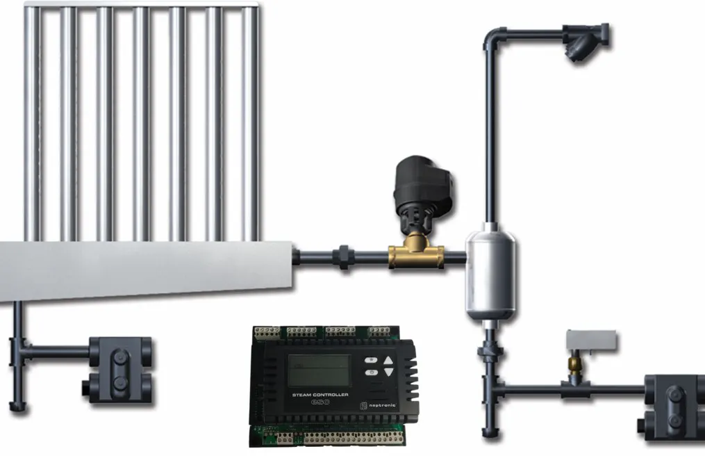
SKE4 as the Steam Source
Where no facility steam is available, steam is generated by the Neptronic SKE4 resistive steam humidifier (5–120 kg/h at 50 Hz) and carried by hose or insulated pipe to an S.A.M., S.A.M.E2 or Multi-Steam™ distributor. Because it can run on RO/DI water, it is a preferred solution in hygiene-critical facilities.
Most Common Mistakes
Distribution mistakes frequently seen in the field, and the right approach:
WRONG
Humidity sensor half a metre behind the distributor; it reads unmixed steam, the control cuts the steam too early and the room stays below target.
RIGHT
High-limit sensor outside the absorption distance, where mixing is complete; control sensor in the room or the return duct.
WRONG
90° elbow right behind the distributor; water collects continuously on the elbow's outer wall and starts dripping into the room.
RIGHT
Elbow outside the absorption distance; if the straight duct is too short, a shorter-distance distributor (S.A.M.E2 or Multi-Steam™) is selected.
WRONG
6 m of uninsulated, sagging hose between unit and distributor; condensate collects at the low point and is carried from the distributor into the duct.
RIGHT
Hose as short as possible (≤ 5 m total for flexible hose), insulated; slope at least 2% on descending sections and at least 15% on rising sections (Neptronic installation manual); condensate trap returns it, no dripping at the manifold.
WRONG
A single short distributor in a 1,200 mm tall duct; steam concentrates in part of the section, the plume lengthens and part of the duct is not humidified enough.
RIGHT
A multi-tube Multi-Steam™ spread across the section, or more than one distributor; steam is spread evenly and the distance shortens.
WRONG
Distributor ahead of the cooling coil; the coil condenses the added moisture again, the drain pan overflows and a hygiene risk appears.
RIGHT
Distributor after the heating and cooling coils, where the air is warmest, with a clear straight duct behind it.
NKT Approach
As Neptronic's distributor in Türkiye, NKT – Nem Kontrol Teknolojileri supplies steam humidifiers and steam distribution systems and provides technical support so that the unit and the distributor are selected correctly together. The data we need for selection are:
- Duct or AHU data: Section dimensions, airflow and the air velocity in the section where the distributor will sit.
- Air conditions: Temperature and RH of the air reaching the distributor, and the target humidity.
- Available straight duct: The distance from the distributor to the first elbow, filter or coil.
- Steam source: Facility steam (SKD), electric generation (SKE4) or steam-to-steam (SKS4).
With these data we support selecting the unit capacity and distributor type together, and the absorption distance is checked against manufacturer data; placement, installation and commissioning are within the scope of the facility's design engineer and installer. Technical service and spare-parts support are also provided.
The steam distribution manifold and the absorption distance are two key topics that decide the field performance of steam humidification systems. Whether the steam the unit produces reaches the space depends on selecting the right distributor, placing it in the right spot and keeping every obstacle out of the absorption distance. Poor design leads to capacity loss, condensate dripping, hygiene risk and, in the long run, duct corrosion.
Correct design combines four rules: (1) the distributor sits after the heating and cooling coils, where the air is warmest and flow is even; (2) the absorption distance is set from manufacturer data, no obstacle sits inside it, and duct humidity is capped with a high-limit sensor; (3) the steam line is kept short, insulated and sloped, and condensate is removed through a trap; (4) in wide sections and short ducts, multi-nozzle or multi-tube distributors (S.A.M.E2, Multi-Steam™) are used instead of a single tube.