A steam humidifier is a device that heats water to its boiling point to produce water vapour and delivers that vapour to an HVAC duct or directly to a conditioned space. It is the most hygienic and tightest-controlled branch of the industrial humidification family, the default solution in sterile or semi-sterile environments such as hospitals, pharmaceuticals, food, museums, print rooms, data centres and sensitive electronics manufacturing. There are two core architectures for steam generation: electrode (Joule heating driven by water conductivity) and resistive (immersion heating elements inside a stainless-steel chamber). This article reviews the operating principle of each, the key differentiators, application matching, and the link between water quality and technology selection.
What Is a Steam Humidifier?
A steam humidifier is a device that produces controlled water vapour and delivers it to an HVAC duct or directly to a space. It heats water to the 100 °C boiling point with an energy input, then injects the saturated vapour into the airstream through a steam distribution manifold; the vapour mixes with the air and releases part of its latent heat, raising both relative humidity and absolute humidity. Thermodynamically the process is isothermal, air temperature remains practically unchanged. This is the key distinction from adiabatic (atomisation) systems: atomisation cools the air by drawing heat from it, while steam generation carries the heat in with the moisture.
A steam humidifier is not a single technology; depending on the energy source and steam-generation architecture, it splits into four main families. Electrode systems make water part of the electrical circuit, current passes through the ions in the water, producing vapour via Joule heating. Resistive systems keep water electrically isolated; Incoloy or stainless immersion heating elements inside a stainless-steel chamber transfer heat directly into the water. Gas-fired systems burn natural gas or LPG and, at large capacities, significantly reduce the required electrical infrastructure. Steam-to-steam systems use the facility's existing high-pressure boiler steam to generate clean steam in a secondary hygienic water loop.
| Dimension | Typical Range | Note |
|---|---|---|
| Capacity | 2 – 1,000+ kg/h | Single unit or cascaded |
| Control band | ±1% – ±5% RH | Depends on architecture and PID tuning |
| Typical electrical draw | ~750 W / kg steam | For electric systems (resistive + electrode) |
| Steam temperature | ≈ 100 °C (saturated) | Isothermal; preserves air temperature |
| Water quality | Potable – RO/DI | Varies by architecture; detailed below |
| BMS integration | BACnet / Modbus / Ethernet | Industrial standard |
Where Is Steam Humidification Used?
Steam humidifiers dominate applications with stringent hygiene requirements, a tight mandatory RH band, or a need for mineral-free process water. The sectoral profile is largely complementary to adiabatic atomisation; the two technologies frequently operate side-by-side in different rooms of the same facility.
- Hospitals and operating theatres: ASHRAE 170 and the Turkish Ministry of Health Hygienic Class regulation hold operating theatres at 50% ± 10% RH; steam must be mineral-free.
- Pharma and cGMP production: 30-50% RH in tablet and capsule rooms; ±5% RH tolerance in ICH Q1A stability cabinets; sterile, mineral-free steam.
- Food production and ripening: Meat, cheese and chocolate ripening rooms; hygienic steam mandatory under HACCP/BRC.
- Museums, archives, libraries: 45-55% RH band for the preservation of wood, paper, leather, textile and metal objects.
- Print rooms and graphic arts: ±3% RH band in offset print halls; paper dimensional stability and static control.
- Data centres and electronics manufacturing: 40-60% RH for ESD and static electricity control.
- Laboratories (QC, ICH stability): tight band control and mineral-free steam.
- Precision rooms (optics, fine mechanics): ±2% RH band or tighter.
Because steam does not lower temperature, the solution does not add cooling load in winter. However, electrical consumption is high compared with atomisation (about 6-10 times higher); for very large capacities (for example a textile mill at 800-1,500 kg/h), a steam-only architecture is rarely optimal.
Core Advantages
Steam humidifiers have five structural advantages over adiabatic technologies. Together they make steam the default choice for hygiene- and precision-driven applications.
Against these five advantages stand two structural limits: high electrical consumption (≈ 750 W/kg) and water-quality-driven maintenance burden (especially in electrode systems). Both can be largely managed through architectural choice (resistive + RO/DI feed, gas-fired, hybrid approach).
How Electrode Steam Humidifiers Work
An electrode steam humidifier makes the water itself part of the electrical circuit. Two or three stainless-steel electrodes inside a plastic cylinder are powered from the mains (typically 380V three-phase). Water provides the conductive medium between the electrodes; current flows through the dissolved salts via ionic conduction. Where the current flows, Joule heating (P = I²R) occurs and water boils; steam leaves the top of the cylinder. The rate of steam production depends on the water level, more water means more active electrode surface and more current. The primary control mechanism in an electrode unit is therefore electronic regulation of the water level.
This architecture is directly dependent on the water's electrical conductivity. Manufacturers typically define a narrow conductivity window, often 125-1,250 µS/cm. Below this window (e.g. RO or DI water), there are not enough ions to carry the current and the device will not run. Above the window, current rises sharply and the result is over-production, foaming and overflow risk. During operation, mineral deposits from electrolysis continually thicken the electrode surface; at some point the electrode is fully coated and the unit signals a cylinder replacement.
The electrode cylinder is by design a single-use plastic consumable. Depending on water hardness, TDS, intensity of use and drain frequency, it is replaced every 6-18 months. The initial purchase price is usually lower than a resistive unit's; however, the 10-year total cost of ownership can climb above the resistive solution quickly due to repeated cylinder changes. Each cylinder change also produces plastic waste, which can be a constraint in facilities with sustainability-reporting obligations.
How Resistive Steam Humidifiers Work
A resistive steam humidifier keeps water fully isolated from the electrical circuit. Steam generation is provided by Incoloy 800 (or comparable high-nickel-alloy) heating elements immersed in a stainless-steel evaporation chamber (typically AISI 304 or 316L). The element heats up under electrical current; heat is transferred to the surrounding water by conduction and convection; once the water reaches boiling point, vapour is produced. The water is not in the same circuit as the element, current flows through the metal sheath of the element and does not touch the water. This simple but decisive distinction removes water quality as an input to system performance.
The chamber is a permanent stainless-steel vessel, not a consumable. Scale and mineral deposits gradually form on the element surface; a tool-free annual maintenance procedure cleans the deposit once or twice a year. In facilities fed by RO water this cleaning cycle is virtually eliminated. Heating elements typically last 5-7 years; replacement is a planned maintenance activity, not a cylinder-style consumable expense.
Resistive systems modulate 0-100%; the element is driven by SCR (Silicon Controlled Rectifier) phase-angle control, and the PID controller continuously regulates steam output. This enables tight bands such as ±1% RH, well below the typical ±5% band of electrode units. Because the architecture is unaffected by changes in water quality, capacity remains stable; seasonal swings in water hardness do not destabilise steam production.
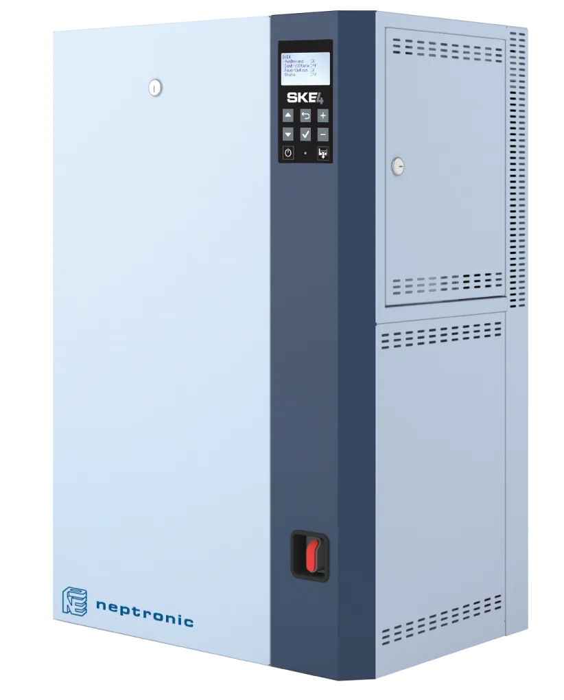
Neptronic SKE4 Resistive: Product Recommendation
The Neptronic SKE4 resistive steam humidifier uses an AISI 304 permanent stainless-steel evaporation chamber, Incoloy 800 immersion heating elements, a tool-free maintenance cover and a patented Anti-Foam Energy-Saving (AFEC) system to run independently of water quality. 2.7 – 136 kg/h capacity ±1% RH control RO/DI compatible No plastic cylinder BACnet / Modbus
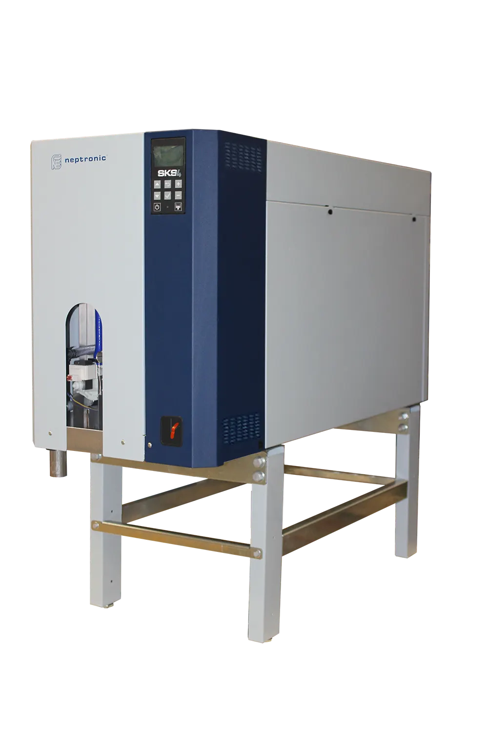
Neptronic SKS4 Steam-to-Steam: Alternative
If the facility already has a high-pressure steam boiler, a steam-to-steam solution stands out for energy efficiency. The Neptronic SKS4 uses boiler steam as its heat source to boil RO/DI water in a secondary stainless-steel chamber; the output is mineral-free clean steam. This is the preferred solution for hospitals, pharma and large food facilities.
Core Difference
The structural difference between the two architectures comes from the role water plays in the electrical circuit: in an electrode system the water is an active conductive element, in a resistive system it is a passive heat sink. This simple difference cascades into water quality, maintenance, control precision and total cost of ownership. The figure below summarises the two operating principles side-by-side.
Figure 1. Electrode vs Resistive Steam Humidifier: Operating Principle
| Criterion | Electrode | Resistive (SKE4) |
|---|---|---|
| Operating principle | Water is part of the electrical circuit; Joule heating. | Element transfers heat directly; water is passive. |
| Conductivity dependence | High, 125-1,250 µS/cm window required. | None, conductivity is not an input. |
| RO/DI compatibility | Incompatible, device will not run. | Ideal, scale practically zero. |
| Chamber / cylinder | Single-use plastic cylinder; replaced every 6-18 months. | Permanent stainless chamber; tool-free annual clean. |
| Control band | ±5% RH (typical). | ±1% RH (PID + SCR). |
| Sustainability | Annual plastic waste burden. | No plastic waste; long-lived chamber. |
| Typical application | Offices, commercial buildings, warehouses (mid-precision). | Hospitals, pharma, museums, print, data centres. |
Which System for Which Application?
Matching an application to a technology requires weighing three axes together: the hygiene/sterility requirement, the required RH control band, the water-quality profile and the existing facility infrastructure (boiler steam, natural gas). The decision matrix below offers a first recommendation for typical cases; the final decision is always confirmed by site engineering analysis.
| Application / Space | RH Band | Water Profile | Recommended System |
|---|---|---|---|
| Operating theatre, cGMP production | 50% ± 5% | RO/DI or facility steam | SKS4 (steam-to-steam) or SKE4 (RO) |
| Museum, archive, library | 50% ± 5% | RO or softened | SKE4 Resistive |
| Precision print, graphic arts | 50-60% ± 3% | Mains or RO | SKE4 Resistive |
| Data centre, electronics manufacturing | 40-60% ± 5% | Mains | SKE4 Resistive |
| Hospital corridor, waiting area | 40-50% ± 5% | Mains | SKE4 Resistive |
| Large textile plant (>500 kg/h) | 65-80% ± 5% | RO/DI | SKH atomisation (adiabatic) |
| Pharma facility with steam boiler | 45-55% ± 3% | Facility steam + RO | SKS4 (steam-to-steam) |
| Large capacity + natural-gas infrastructure | General HVAC | Mains / RO | SKG4 (gas-fired) |
A hybrid approach where different rooms in a single facility are fed by different technologies is common: in a pharma plant, for instance, SKS4 for the main production room, SKE4 for packaging and SKG4 (gas-fired) at the warehouse entrance can yield an economic optimum. NKT project engineering sizes this mix on real consumption data.
Why Water Quality Drives Selection
Water quality is the decisive input in steam-humidifier selection because the two architectures respond differently to water parameters. Electrode systems depend on conductivity, so the dissolved-solids content, hardness and mineral profile of the water directly drive capacity, cylinder life and drain frequency. Resistive systems are independent of conductivity; only scale build-up affects the annual maintenance cycle. With RO/DI feed, even that burden is largely eliminated for the resistive architecture.
| Water Type | Conductivity (µS/cm) | Hardness (°fH) | Electrode | Resistive (SKE4) |
|---|---|---|---|---|
| Purified (RO / DI) | 5 – 25 | 0 – 1 | Does not run | Ideal (minimal maintenance |
| Softened (ion exchange) | 300 – 800 | 0 – 2 | Marginal) foaming risk | Compatible |
| Typical urban mains (medium) | 400 – 700 | 10 – 25 | Compatible (cylinder life 12-18 mo | Compatible) annual clean |
| Hard mains (Anatolian) | 700 – 1,200 | 25 – 45 | Cylinder life 6-10 mo | Compatible (clean 2× yearly |
| Very hard / well water | 1,200 – 2,000 | > 45 | Exceeds window) foaming | Compatible (RO pretreatment advised) |
Before any investment decision, a water analysis must be performed; at a minimum it should report conductivity, hardness (°fH), TDS, chloride, silica and alkalinity. These five parameters underpin both cylinder-life and maintenance-load calculations. In NKT's proposal process, the customer's water analysis is combined with the psychrometric calculation to produce the technology match.
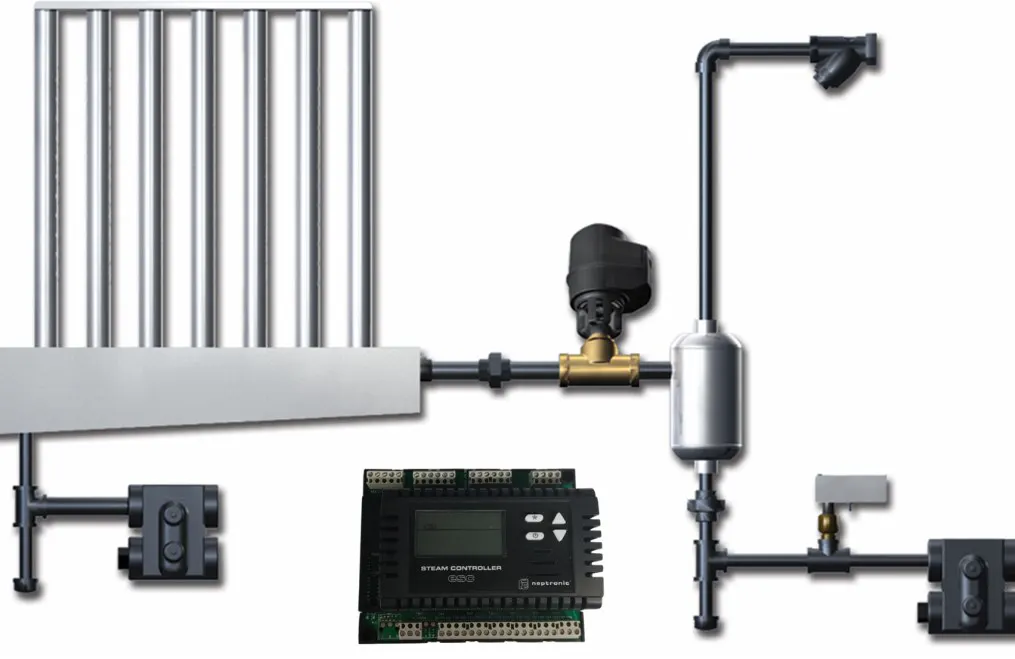
Steam Distribution and Absorption Distance
Producing steam is not enough; the generated steam must be distributed evenly into the airstream and fully absorbed inside the duct. Otherwise condensate forms on the duct wall, creating dripping and microbiological-contamination risks. The absorption distance is the distance after the steam injection point within which the steam is completely converted to invisible water vapour. A typical steam distribution manifold is sized for 1-2 m absorption distance; the actual value varies with air temperature, air velocity, steam-generation rate and the nozzle pattern of the manifold.
k: nozzle design coefficient (manufacturer-specific)
Figure 2. Steam Humidification System Flow (Water → Chamber → Steam → Distribution → Duct)
The steam distribution manifold should sit perpendicular to the airflow and as high in the duct as possible; nozzles oriented 90° to the airflow give the most uniform dispersion. Multi-Steam distribution shortens the absorption distance in large duct cross-sections; this solution sits in the Neptronic distribution family.
NKT / Neptronic Approach
NKT Nem Kontrol Teknolojileri is Neptronic's official distributor in Türkiye and delivers end-to-end engineering for steam humidification, high-pressure atomisation and adiabatic duct systems. The four core steam solutions in the portfolio are positioned as follows:
- SKE4, Resistive steam (2.7-136 kg/h). Single-site facilities, hospitals, pharma, print rooms, museums, data centres.
- SKS4, Steam-to-steam. Facilities with an existing high-pressure boiler; clean steam.
- SKG4, Gas-fired steam. High capacity + natural-gas infrastructure.
- SKD / Distribution, Steam distribution manifolds and multi-nozzle (Multi-Steam) solutions.
The NKT project flow runs in six steps: site analysis, target definition, load calculation, technology selection, commissioning and validation. Steam-distribution manifold design, absorption-distance simulation and capacitive sensor placement are standard deliverables in the project handover. In most projects the water-analysis result is combined with RO pretreatment to produce a clear 10-year TCO.
Steam humidifiers are the dominant solution for applications that demand hygiene and a tight control band. The electrode architecture depends on water conductivity, consumes plastic cylinders and works in a relatively wider RH band (±5%); its low initial cost makes it popular in offices and commercial buildings. The resistive architecture is independent of water quality, uses a permanent stainless chamber and can control within ±1% RH; it stands out structurally in hospitals, pharma, museums, precision print and data-centre applications. The two systems are not substitutes, each is designed for a different application profile.
The right choice starts with three questions: (1) What hygiene and control-band requirement does the application have? (2) What is the facility's water quality and existing infrastructure (boiler steam, natural gas, RO system)? (3) How does the 10-year TCO balance between cylinder/element replacement and energy cost? Combining the answers with a psychrometric calculation clarifies the right device type and capacity. The NKT engineering approach gives the answers up-front; equipment selection is the last step, emerging from the engineering analysis.