Definition
A stainless-steel manifold with one or several arms that distributes steam from a steam humidifier evenly across an AHU duct or directly into a space.
Detailed Explanation
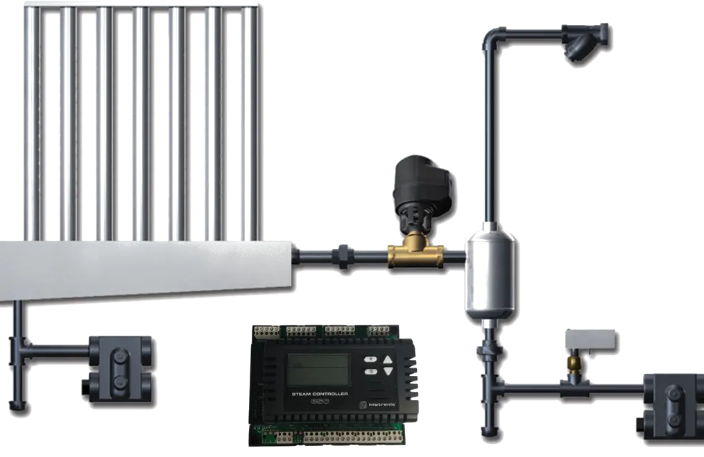
A steam distribution manifold sits between the humidifier's steam-generation chamber and the AHU duct (or the space) and is built from stainless steel (AISI 304/316). Steam exits through small jets spaced evenly along the manifold; this design promotes homogeneous mixing with the airstream.
Configuration follows duct width: a single arm for ducts under 600 mm, a single long arm for 600–1500 mm, a multi-arm parallel manifold above 1500 mm. Each arm is typically heated (kept above 4–8°C to prevent condensation) or the steam pipe is laid with a minimum 1% slope to allow condensate return. The jet direction can be parallel or 90° to the airstream; parallel orientation yields a shorter absorption distance.
Why It Matters
A correctly designed steam manifold delivers short absorption distance, zero condensate accumulation, and uniform RH distribution. A bad design causes three typical problems: (1) Condensate dripping — if the manifold is poorly insulated, droplets form on the inner surface and fall to the duct floor; that creates a hygiene risk (Legionella), corrosion, and damage to wood/electronics under the duct. (2) Insufficient absorption — a short-arm manifold in a wide duct concentrates steam on one side and starves the other; the downstream sensor reads the wrong RH and the control loop becomes unstable. (3) Wall wetting — when steam exits too close to the duct wall, condensation on the wall causes corrosion.
Manifold selection is a standard step in NKT design; OEM tools (Neptronic Distance Calculator, humidifier control software) recommend manifold model and quantity from duct dimensions, air velocity, temperature, and target RH.
Practical Example
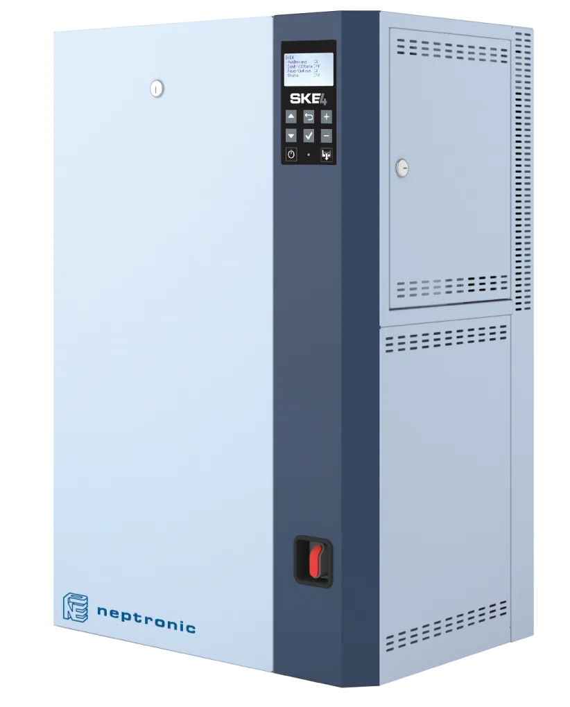
A pharmaceutical plant in Izmir: AHU duct 1200×600 mm, air velocity 2.5 m/s, supply air 22°C, target RH 50%, humidifier Neptronic SKE4-90. A single Neptronic SKD-AC manifold arm (1100 mm long, 18 jets) was specified; the absorption-distance calculation returned 1.8 m, and the downstream RH sensor was placed 2 m past the manifold in the straight section. Commissioning showed zero condensate, with RH measured at four points (left, mid-left, mid-right, right): 49.8 / 50.2 / 50.1 / 49.7%. Uniformity is ±0.3%, well inside the ±2% target band.
Engineering Note
Steam-manifold selection criteria: (1) Length = 75–85% of duct width; shorter leaves edge zones starved, longer puts jets too close to walls and risks condensate. (2) Jet count and orientation — proportional to steam mass flow and air velocity, per OEM tables. (3) Material — AISI 304 stainless steel by default; AISI 316 in chloride or corrosive environments. (4) Manifold heating — for long (>3 m) main steam pipes or installations far from the duct, a jacketed (insulated) manifold prevents droplet formation. (5) Manifold-to-sensor distance — the sensor must sit beyond the absorption distance and inside a well-developed flow region; never just before an outlet damper, an elbow, or a duct expansion.
NKT Application Link
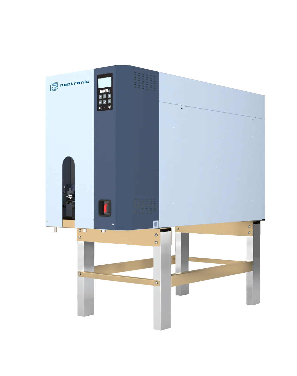
NKT supplies the Neptronic SKD steam-distribution manifold family alongside Neptronic steam humidifiers (SKE4, SKS4, SKG4); variants include SKD-AC (outdoor air-jacketed), SKD-CK (standard AHU duct), and SKD-DR (direct-room). Manifold length is built to order from 200–3000 mm in 100 mm increments, with 4–100+ jets per the design. During commissioning, the NKT engineering team calculates absorption distance per manifold; the downstream sensor location is added to the manifold documentation. The NKT - Climate Track platform delivers 4–8 point RH-uniformity trend logs, and manifold performance is validated annually.