Definition
The system architecture that jointly manages indoor air quality, temperature, humidity, and airflow in buildings and industrial facilities. It comprises air handling units (AHUs), heating/cooling coils, humidity control equipment, ductwork, and automation controls. Industrial humidity control solutions (condensation or silica gel rotor units, steam humidifiers) are usually integrated with the existing HVAC system or operated independently.
Detailed Explanation
An HVAC system combines four primary functions: (1) heating — raising indoor air temperature to comfort or process targets in winter, (2) cooling — removing summer or process heat loads, (3) ventilation — bringing in fresh outdoor air and exhausting contaminated indoor air, (4) humidity control — maintaining a relative humidity or dew point target (dehumidification + humidification).
The architecture is typically organized around an AHU (Air Handling Unit): outdoor air + return air mixer, F7/F9 + HEPA filter cascade, heating coil (hot water or electric), cooling coil (DX or chilled water), humidifier (steam/atomization), silencer, fan, and ductwork distribution. In industrial HVAC, the dehumidifier is often a separate unit positioned in series/parallel; for low-dew-point applications such as lithium battery dry rooms or freeze-dryer storage, a silica gel rotor dehumidifier is integrated downstream of the AHU.
Practical Example
HVAC design for a 5,000 m² pharmaceutical production facility:
Requirements: • Production corridor: 22°C ± 1, 45 ± 5% RH, ISO 8 cleanroom • Granulation room: 22°C ± 1, 35 ± 5% RH (low humidity for hygroscopic active ingredients) • Tablet press: 22°C, 40 ± 5% RH • Storage: 18°C, 50 ± 10% RH
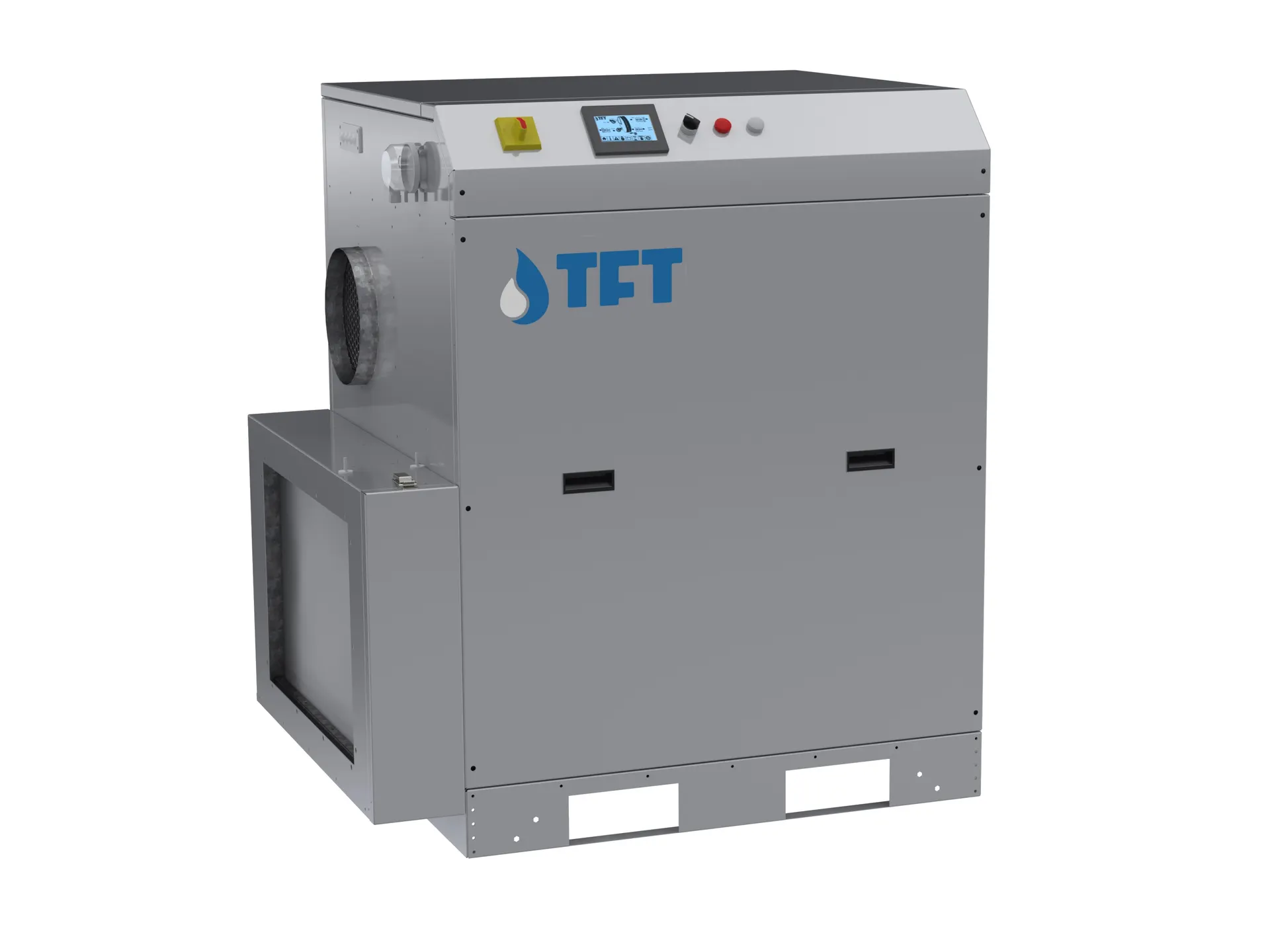
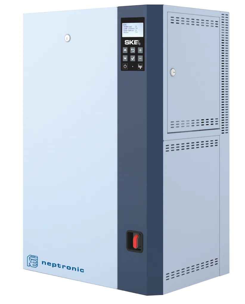
Solution: • Central AHU: 25,000 m³/h, F7+F9 filters, hot/chilled water coils, Neptronic SKE4 electric steam humidifier (250 kg/h, hygienic steam) • Additional silica gel rotor dehumidifier for granulation (TFT AD1000, 1,000 m³/h, –10°C dp target) • Control: independent PID loops per zone via BMS, ICH Q1A-compliant data logger • Redundancy: N+1 fans for critical zones, AHU bypass damper
Energy consumption: 35% heating, 25% cooling, 15% dehumidification, 10% humidification, 15% fan + other. Steam from the existing plant utility was used for reactivation, reducing electricity consumption by 40%.
Engineering Note
The 5 most common mistakes in HVAC + dehumidifier/humidifier integration:
1. The dehumidifier is fed from the main duct, not via AHU bypass — the full fresh-air moisture load hits the unit and capacity falls short. Correct: separate units for outdoor pre-dehumidification and indoor return. 2. The humidifier is placed after the cooling coil — droplet carryover occurs. Correct: after the heating coil, before the fan. 3. A single setpoint for multiple zones — running granulation and storage on the same setpoint wastes energy and produces out-of-spec operation. Independent PID loops are mandatory. 4. Cheap selection of reactivation energy — electric vs gas vs steam? Annual OPEX varies 4–6× depending on site utilities. Sterling: use existing plant steam first, then waste heat recovery, electricity last. 5. No BMS monitoring — HVAC is installed but no trend and alarm system. In this case 20–35% energy waste + out-of-spec operation goes unnoticed. Modbus/BACnet integration must be standard.
The NKT engineering team supports HVAC + humidity control integration design, equipment selection, installation, and commissioning. In critical processes such as lithium battery, pharmaceutical, and semiconductor, HVAC design is the primary engineering decision — late additions are both expensive and ineffective.