Definition
A real-time digital control device that reads sensor inputs, processes logic, and controls actuators in industrial processes. In industrial dehumidifiers, compressor, fan, defrost, rotor, heaters, and control valves are coordinated by a single PLC. Connects to BMS via Modbus, Profinet, or BACnet.
Detailed Explanation
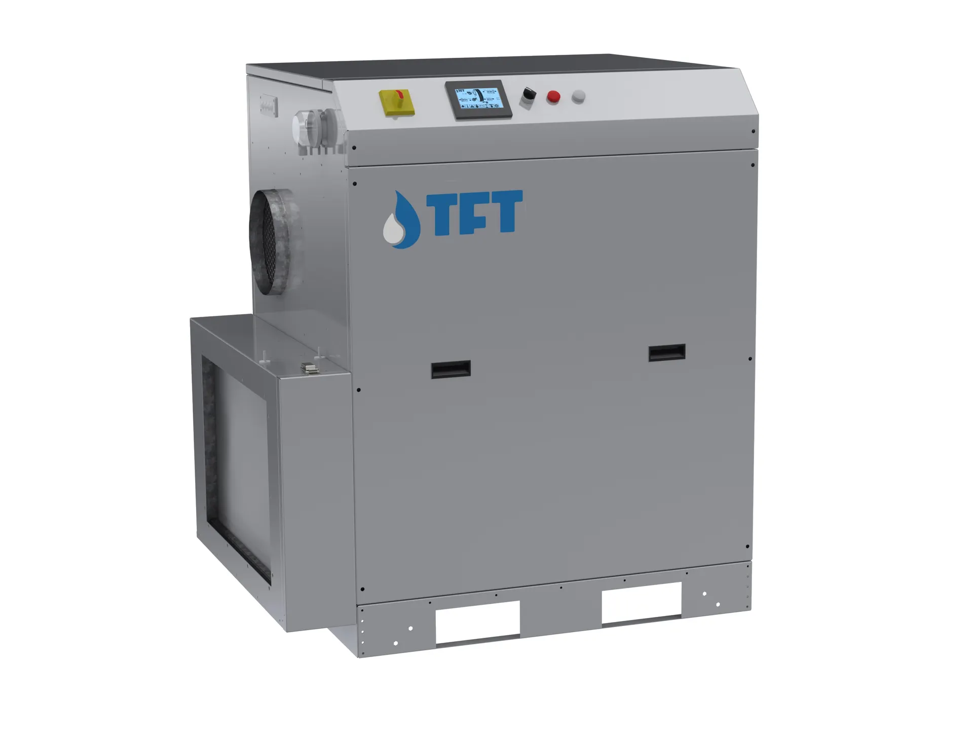
PLC (Programmable Logic Controller), invented in 1968 by General Motors to replace relay-based control panels, is an industrial computer. Today it is the brain of every industrial dehumidifier. In a typical TFT silica gel rotor unit, the PLC manages:
• Rotor rotation speed (8–20 rev/h, scaled to outdoor load) • Reactivation heater modulation (PID loop controlling outlet temperature) • Fan inverter speed (process airflow setpoint tracking) • Bypass damper position (side-stream control) • Sensor data acquisition (RH, temperature, pressure, dp) • Alarm handling (capacity drop, sensor failure, high temperature, loss of flow) • Data logging and trend analysis • BMS communication (Modbus RTU/TCP, Profinet, BACnet)
PLC programming is typically done in ladder logic (LD), structured text (ST), or function block diagram (FBD) (IEC 61131-3 standard). Modern PLCs ship with touch HMIs (Human-Machine Interface); the operator can change setpoints, view alarms, and pull trend charts directly from the panel.
Practical Example
PLC programming example in a TFT AD3000 silica gel rotor unit:
Inputs (sensors): • Process air inlet RH/T (industrial-class RH/T sensor) • Process air outlet dp (low dew-point sensor) • Reactivation air inlet/outlet temperatures (Pt100) • Fan differential pressure (flow sensor) • Rotor rotation speed encoder
Outputs (actuators): • Reactivation heater SCR modulation (0–100%) • Process fan inverter (0–50 Hz) • Reactivation fan inverter (0–50 Hz) • Rotor motor inverter (rev/h control) • Alarm relays (to BMS)
Control algorithm: 1. Target dp –10°C; actual dp measured 2. Deviation > +2°C → raise reactivation temperature to 110°C (max 140°C) 3. Deviation > +5°C → increase rotor rotation from 12 to 16 rev/h 4. Deviation < –2°C → reduce reactivation heater (energy saving) 5. If target not held within 30 min → alarm "performance degraded" 6. All data CSV-logged at 30 s + Modbus to BMS
This simple control loop saves 20–30% energy (vs fixed-setpoint operation) and detects performance degradation early.
Engineering Note
Six important decisions in PLC design:
1. Brand selection — industrial PLC, compact PLC, automation system Modicon are most common. TFT Italy units typically use BMS/PLC automation system or automation system PLCs. For long-term spare-parts security, BMS/PLC automation system is safest. 2. I/O count — scales with capacity. 16 DI/DO + 8 AI/AO sufficient for a 1,000 m³/h unit; 64+ DI/DO + 32 AI/AO for 25,000 m³/h. 3. HMI type — 7" touchscreen is standard; 12–15" panels for complex sites. Remote access via webserver is a modern feature. 4. Communication protocol — Modbus TCP is the most universal for BMS compatibility; BACnet IP is smarter but may require licensing; Profinet is excellent in BMS/PLC automation system ecosystems. 5. Redundancy — for critical processes, redundant CPU + redundant network (PROFINET MRP ring); CAPEX rises 30–40% but single-point failure is eliminated. 6. Programming language — ladder logic is the most readable for operator teams; structured text suits complex math (PID, regression). A hybrid approach is common.
At NKT we deliver PLC programming, BMS integration, and remote monitoring services for TFT units; all units ship with Modbus TCP as standard, with additional protocol requirements handled per project.