In electrode steam humidifiers, the cylinder is, in most units, a plastic consumable replaced together with its electrodes at intervals. These intervals vary widely from site to site with the water's conductivity and mineral content, operating hours and control profile. Two facilities with the same device, the same capacity and the same shift pattern can see cylinder life differ markedly. This article reviews which parameters drive cylinder life, why it is hard to predict, and how the structural uncertainty can be removed, via the resistive alternative.
What Does the Cylinder Do?
In electrode steam humidifiers, the cylinder is the plastic body that contains the electrodes and the water. Two or three stainless-steel electrodes are mounted inside it; mains voltage (single- or three-phase, depending on the unit) is applied to the electrodes, and the water completes the circuit between them. Current flows through the dissolved salts in the water by ionic conduction; Joule heating (P = I²R) boils the water and steam exits the top of the cylinder. The amount of steam produced is directly proportional to the active conductive water volume, in other words, to the water level and the ion density in the water.
The cylinder body is moulded from a high-temperature polymer (typically polypropylene or PPS). In most units the cylinder is replaced as one piece together with its electrodes: the layer of scale and mineral deposits that forms on the electrode surface gradually coats it; current flow into the water drops, the water level rises, and once rated output can no longer be reached even at the top level, the cylinder is replaced. Cleanable cylinder types that can be opened also exist, but their electrodes still wear and are renewed over time. With one-piece cylinders, the replacement is not a single wear part but almost the entire steam-generation module.
At equivalent capacity, the initial cost of electrode and resistive units is often similar; the electrode architecture, however, transfers a structural consumable cost into the operating phase. The NKT catalogue does not include an electrode model; this article is provided so that the technology can be understood independently and the right alternative recommended.
Why Cylinder Life Is Not Constant
It is hard to express cylinder life with a single number, because life depends simultaneously on the chemistry of the water and the usage profile of the device. A single "typical life" figure therefore loses validity outside specific conditions. Two side-by-side units in the same facility can show different lives if the shift/load profiles differ.
Six core factors drive cylinder life: (1) the water's electrical conductivity, (2) water hardness and scaling tendency, (3) TDS and dissolved solids, (4) drain frequency and drain volume, (5) foaming tendency (silicates, organics), and (6) usage intensity (hours/day and load profile). These factors are discussed in sequence below; the final sections position life-extension strategies and the resistive alternative.
Figure 1. Mineral Build-up Inside an Electrode Cylinder Over Time
How Conductivity Affects Cylinder Life
An electrode cylinder operates within a specific conductivity window (typically 125-1,250 µS/cm). The window is defined by the manufacturer based on architectural design. Below the window, current is insufficient and the unit cannot generate steam; above it, current rises sharply, driving over-production, foaming, overflow and rapid scale deposition on the electrodes.
Below the window (< 125 µS/cm, including RO/DI water) the cylinder does not have a short life; the unit simply does not run. Within the window, the higher the water's mineral load, the faster the electrodes are coated and the shorter the cylinder life. The figure below shows this relationship qualitatively; no scale in months is given, because life depends on the facility's water and steam output.
Figure 2. Water Conductivity × Cylinder Life Relationship (Electrode)
Because mains-water conductivity and hardness vary widely by region and source, no regional cylinder-life figure can be given; the facility's own water analysis should be the basis.
Hardness and Scaling
Water hardness is the total content of calcium (Ca²⁺) and magnesium (Mg²⁺) ions in water; in Türkiye it is typically measured in French degrees (°fH). 1 °fH = 10 mg/L CaCO₃ equivalent. Hardness affects cylinder life mainly through scaling.
Scaling: as water heats to 100 °C, the solubility of dissolved calcium carbonate (CaCO₃) drops; in the high-temperature region directly at the electrode surface, the minerals precipitate as solid deposit. Over time this deposit forms an insulating layer between electrode and water; current flow into the water drops and a higher water level is needed to maintain the same capacity. Hardness and conductivity, however, are separate parameters: conductivity comes not from hardness but from the sum of all dissolved ions, and must be measured separately. Softened water, for example, keeps its high conductivity despite low hardness; conductivity therefore cannot be derived from hardness.
| Hardness Class (approx.) | °fH | Scale Load for the Same Steam Output |
|---|---|---|
| Very soft | 0 – 4 | Very low |
| Soft | 4 – 8 | Low |
| Moderately hard | 8 – 14 | Medium |
| Hard | 14 – 25 | High |
| Very hard | > 25 | Very high |
TDS and Dissolved Solids
TDS (Total Dissolved Solids) is the total weight of all dissolved inorganic and organic components in water; expressed in mg/L. In addition to all hardness components, it includes other dissolved salts such as sodium, chloride, sulphate, silica and nitrate. Therefore two waters with the same hardness can have different TDS values.
In an electrode cylinder, TDS jointly drives water conductivity and the rate of deposition on the electrode surface. As water boils in the cylinder, TDS concentrates by the same fraction as the evaporated water, eventually the dissolved solids reach saturation and precipitate. This concentration cannot be controlled without draining; drain frequency is covered in the next section.
S: steam flow, D: drain flow (feed = S + D). Example: if 10% of the feed is drained, the concentration in the cylinder is about 10 times the inlet value (precipitated scale and droplet carry-over neglected).
Without draining, concentration rises indefinitely → silica precipitation, foaming and uncontrolled current.
In waters with high silica content (some well waters, geothermal-influenced sources), silica deposits form a deposit that is harder and more tightly adherent than ordinary scale. In these waters cylinder life shortens faster than predicted, and cleaning the plastic cylinder is not feasible (silica deposits are hard to dissolve even with chemical acid).
Drain Frequency and Cylinder Life
Electrode units periodically drain automatically: they discharge a portion of the concentrated water to the drain and refresh with fresh water. This keeps TDS and hardness concentration inside the cylinder under control. Drain frequency is normally set automatically by the unit's firmware; in models with manual adjustment, it is calibrated to the facility water.
Very infrequent draining increases concentration and quickly "tires" the cylinder; very frequent draining increases water consumption and reduces energy efficiency (cold water is heated after each drain). The optimum frequency is a joint function of conductivity, hardness and usage intensity. Some design optimisations that aim to minimise drain volume can shorten cylinder life; aggressive draining in the other direction increases water consumption. In practice facilities iterate to find this balance based on water/energy costs.
Why Does Foaming Occur?
Foaming is the formation of a bubble layer on the water surface. In an electrode cylinder, foaming occurs when organic compounds, silicates, phosphates or certain water-softening/treatment chemicals in the water alter surface tension at high temperature. The chain is: (1) the foam layer reaches the high-level sensor in the cylinder, (2) the unit reads this as a high water level and stops filling or drains, (3) the real water level, and with it the steam output, fluctuates, (4) water droplets and minerals can be carried with the foam into the steam line.
Foam and droplet carry-over are not unique to electrode units; they can occur in both electrode and resistive units and are limited in both by regular draining and foam control. The Neptronic SKE4 resistive humidifier, for example, has the patented Anti-Foaming Energy Conservation (AFEC) system. However, if the foaming trigger sits in the water source (wrong treatment chemical, high silicates), the control system does not offer a permanent fix; the source or the treatment must be reviewed.
Wrong Water Treatment
Wrong water-treatment selection is among the most damaging structural errors for cylinder life. Three common treatment choices and their consequences for electrode units:
- Reverse osmosis (RO) water: Drops conductivity well below the band (5-25 µS/cm). The electrode unit will not run, RO water is the wrong feed for electrode systems.
- Deionised (DI) water: Same issue as RO, conductivity is insufficient and the unit does not operate.
- Sodium-based softener: Lowers hardness by exchanging calcium and magnesium for sodium; conductivity does not change noticeably. Sodium salts do not form scale but concentrate in the cylinder; foaming tendency and drain demand can rise. Suitability is determined by the unit manufacturer's feed-water requirements.
For this reason, when investing in a new electrode unit, water treatment must be decided together with equipment selection. If a facility already has an RO system, an electrode unit is the wrong choice; the resistive (SKE4) is preferred directly. This is one of the costliest design mistakes to undo later.
Usage Intensity and Operating Profile
Cylinder life is consumed not by elapsed hours but by total steam produced (kg steam). A 24/7 facility burns through cylinders much faster than a single-shift facility. A 24/7 profile at nominal capacity versus an averaged 40%-load profile across the day can differ in cylinder life several-fold.
The cylinder-swap frequency should therefore be assessed from the facility's real steam-consumption profile (in annual kg).
| Operating Profile | Annual Steam (kg) | Typical Cylinder Life | Annual Swaps |
|---|---|---|---|
| Office / commercial, 8/5 shift | 2,000 – 4,000 | Long | Low |
| Hospital corridor, 24/7 low load | 5,000 – 10,000 | Medium | Medium |
| Print / production, 16/6 shift | 10,000 – 25,000 | Short | High |
| Continuous production 24/7 | 30,000 – 80,000 | Very short | Very high |
Cylinder Consumable Cost
Cylinder consumable cost can be a significant line item in 10-year TCO. The 10-year cylinder line is calculated as annual swaps × cylinder price × 10; in hard-water, high-duty facilities it grows quickly.
Each cylinder swap also adds maintenance labour, warehouse logistics and the cost of handling spent cylinders as waste. This waste may sound small, but facilities with sustainability reporting account for it together with similar line items.
Extending Cylinder Life
There is a structural limit to extending electrode cylinder life; the architecture itself limits it through water quality and use. To approach the longest life within these limits, four operating practices help:
- Correct feed water: A softener lowers hardness but does not set conductivity; the feed water's compliance with the unit manufacturer's conductivity and quality requirements is confirmed by water analysis. RO/DI is not appropriate; the unit will not run.
- Periodic water analysis: At regular intervals and especially at seasonal changes, check conductivity, hardness, TDS, chloride, silica, alkalinity.
- Drain-frequency optimisation: The manufacturer's factory setting may be too aggressive or too infrequent for the facility water; it is adapted to the facility water following the manufacturer's instructions.
- Regular visual inspection: At the intervals in the manufacturer's instructions, inspect the cylinder electrical connections, drain line and level sensor; catch foaming or mineral precipitation early.
Even with all of these practices, the cylinder remains a consumable. The structural fix is to change the architecture.
Resistive Alternative
The structural fix for cylinder consumable cost, drain-water loss and plastic-waste problems is to switch to a resistive steam humidifier architecture. In a resistive unit there is no cylinder; steam generation takes place in a long-lasting, cleanable stainless-steel steam tank where heating elements are immersed in the water. Water is not part of the electrical circuit; conductivity, hardness and TDS do not affect operation.
Instead of a consumable, the stainless steam tank is cleaned tool-free at intervals that depend on water quality (with RO feed this cleaning is greatly reduced). The heating elements are long-lived; replacement is a planned maintenance activity rather than a yearly consumable expense. Plastic waste production is zero.
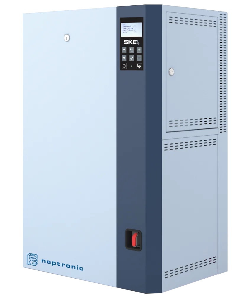
| Dimension | Electrode (cylinder) | Resistive (SKE4) |
|---|---|---|
| Consumable | Plastic cylinder (interval depends on water quality) | None (permanent stainless steam tank) |
| Element / cylinder life | Frequent swaps, depending on water quality and use | Long heating-element life |
| Water-quality dependence | Conductivity window required | None (every water type works) |
| RO/DI feed | Does not run | Ideal, minimal maintenance |
| Plastic waste | Spent cylinders | None |
| Control accuracy (Neptronic data) | ±5% RH (on/off control) | ±1% RH (modulating control) |
| 10-year consumable cost (mid-capacity) | Cylinder count × unit price (high) | Element + cleaning only (low) |
NKT Approach
The NKT – Nem Kontrol Teknolojileri portfolio does not include an electrode unit; the structural consumable-cost, water-quality dependence and plastic-waste issues are considered engineering-solvable, and the steam portfolio is built on Neptronic SKE4 resistive, SKS4 steam-to-steam, SKG4 gas-fired and SKD direct injection families.
At the equipment-selection stage NKT reviews the facility's (a) water-analysis report, (b) existing/planned treatment system, (c) expected annual steam consumption, (d) required RH control band and (e) hygiene/sterility requirements, and the right technology is matched. Where cylinder costs are high, the resistive solution (SKE4) often comes out ahead on total cost; where the maths favours other architectures, alternatives (SKS4 with facility steam, SKG4 with natural gas) are considered.